Digital Monitoring Products CellCom Installation Guide
2
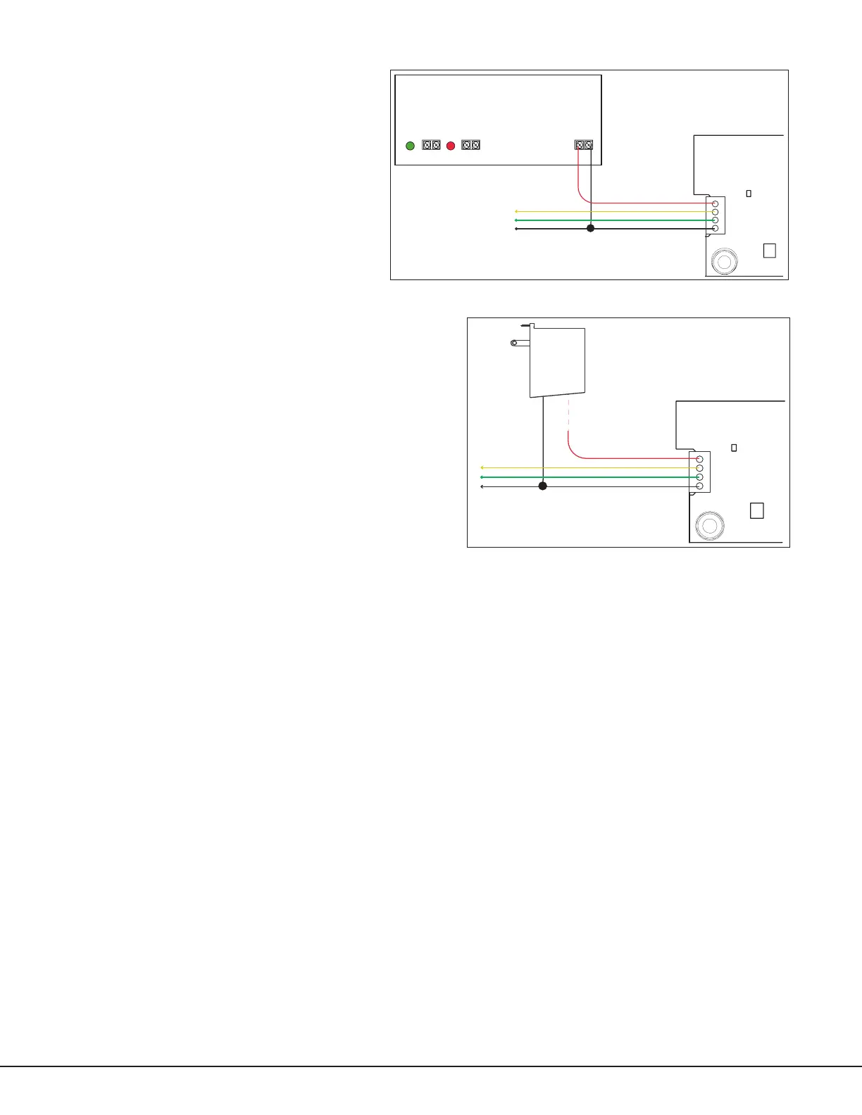
Connecting the Optional Auxiliary Power Supply
Use the following steps when connecting an optional
auxiliarypowersupplytotheCellComRT:
1.ConnecttheRedwire(auxiliaryPower)to
thetopCellComRTJ22terminalposition‘R’
andtotheDCpositiveterminal(+)ofthe
powersupply.SeeFigure3.
2.ConnecttheBlackwire(ground)tothe
bottomCellComRTJ22terminalpositionand
totheDCnegativeterminal(-)ofthepower
supply andtotheLXheader(J22)onthe
XR100/XR500Seriespanel.SeeFigure3.
Connecting the Optional Plug-in Transformer
WhenusinganoptionalModel376plug-inDCpowersupply,
mount the CellComRT near a wall outlet. Use the following steps
toconnecttheplug-inpowersupplytotheCellComRT:
1.Removethebarrelconnectorfromthe376powersupply.
2.Connecttheplug-inpowersupplyBlackwirewithWhite
stripestothetopCellComRTJ22terminalposition‘R’.
SeeFigure4.
3.Connecttheplug-inpowersupplysolidBlackwireto
thebottomCellComRTJ22terminalpositionand to the
LXheader(J22)ontheXR100/XR500Seriespanel.See
Figure4.
4.Plugthepowersupplyintoa110VoltACoutletnot
controlled by a switch.
Programming/Activation
Cellular Service is required before using the CellComRT for signal transmission. Using Remote Link panel
communicationprogramming,selectCELLasoneoftheCommunicationpaths.TheCellComRTcomeswithaSIM
cardreadyforactivationwithSecureComWireless,LLC.Moreinformationisavailableatwww.securecomwireless.
comorrefertotheRemoteLinkGuide(LT-0565).Or,useaSIMcardprovidedbytheGPRScarrierofyourchoice.
LED Indicator
The CellComGreenTransmitLEDlightasheswhentransmissionisbeingmadebetweentheCellComRTandthe
panel.
Diagnostics
The XR100/XR500 Series panels provide a Diagnostics function to test Communication integrity and the Cellular
SignalstrengthoftheCellComRT.TouseDiagnostics,resetthepanel,entertheDiagnosticscode2313(DIAG),and
pressCOMMAND.
Communication Status
SelectCOMMSTATUSfromtheDiagnosticsmenu.TheXR100/XR500panelstesttheCellComRTforthefollowing
items:
•CellComOperating •CellularTowerDetected •APN(AccessPointName)Correct
•SIMCardInstalled •SIMCardRegistered/Active •CommunicationPathIntegrity
Cellular Signal
SelectCELLSIGNALfromtheDiagnosticsmenu.TheXR100andXR500Seriespanelstestandindicatethestrength
ofthesignalusingabardisplay.Onebarindicatingaweaksignal.Sevenbarsindicatingastrongsignal.Ifthebars
indicatesaweaksignal,optionstocorrectthisproblemincluderelocatingtheCellComRTassemblyorextendingthe
CellComRTantennacoaxusingaModel381CoaxExtension.
Red—Auxiliary Power
Yellow—Data In
Green—Data Out
To LX Header (J22) on
XR100/XR500 panel
Black—Ground
Battery
Transmit LED
J22
J4
CellComRT
376
DC Plug-in
Power
Supply
Black Wire with
White Stripes
Solid
Black
Wire
Figure 4: Optional Plug-in Transformer Installation
502-12 Power Supply
J2
J3
J5
AC
+ BAT –
+ DC –
Green
LED
AC
Red
LED
DC
Red—Auxiliary Power
Yellow—Data In
Green—Data Out
To LX Header (J22) on
XR100/XR500 panel
Black—Ground
Battery
Transmit LED
J22
J4
CellComRT
Figure 3: Optional Auxiliary Power Supply Installation
 Loading...