714/715 Installation Guide | Digital Monitoring Products 3
4
Set the Module Address
714 and 715 Zone Expansion Modules use two rotary switches (TENS and ONES) to set the module address. For
keypad bus addresses, set the switches to match the device address. For LX‑Bus addresses, set the switches to
match the last two digits of the addresses. For example, for address 02 set the switches to TENS 0 and ONES 2 as
shown in Figure 4. For more information, refer to Table 2 and Table 3.
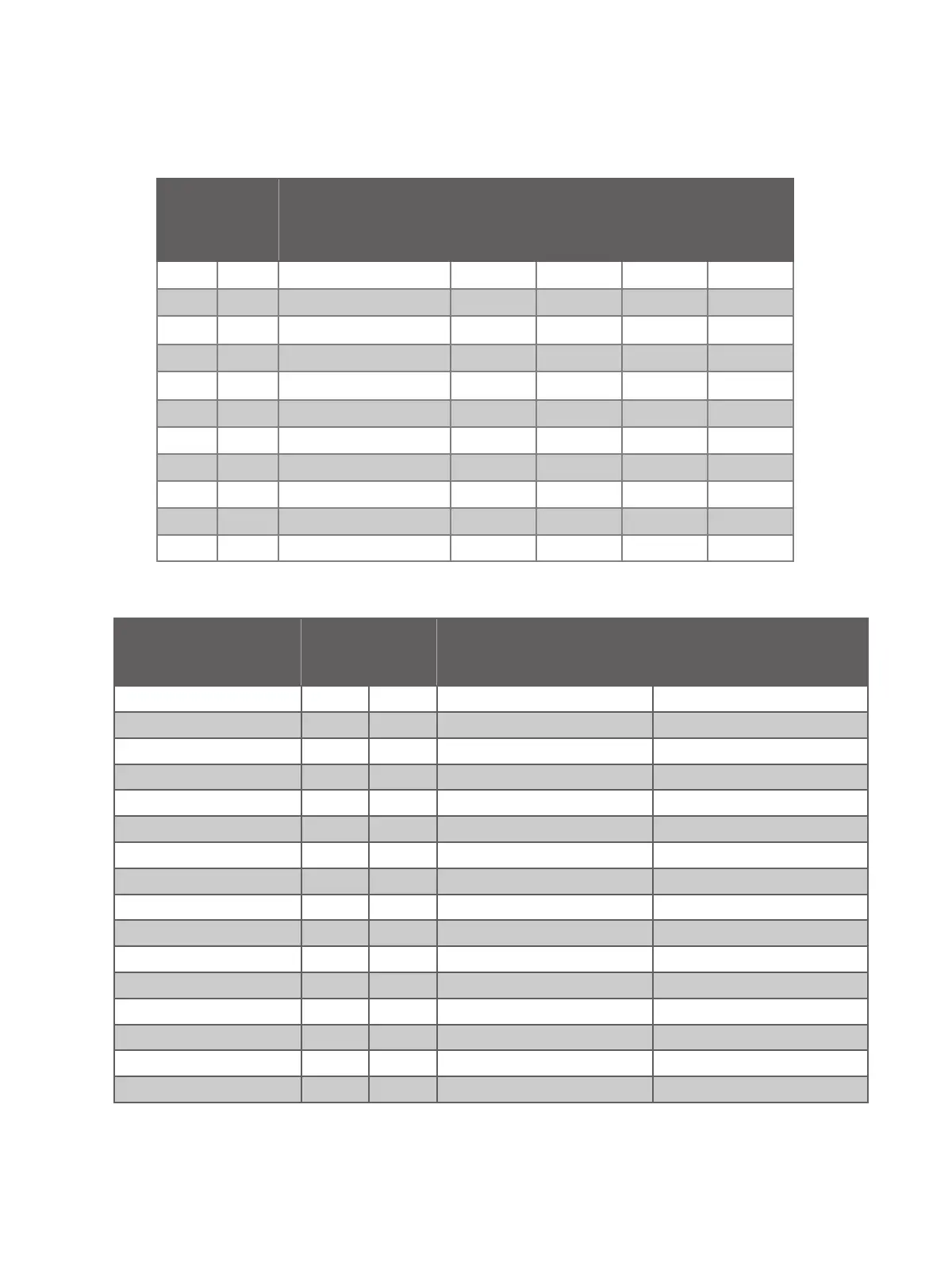
SWITCH
XR SERIES, XF6 SERIES
FIRE, AND XT75
CONTROL PANELS
XR550 AND XF6-500 CONTROL PANELS
TENS ONES LX/LX500 LX600 LX700 LX800 LX900
0 0 500 600 700 800 900
0 1 501 601 701 801 901
0 2 502 602 702 802 902
0 3 503 603 703 803 903
0 4 504 604 704 804 904
... ... ... ... ... ... ...
9 5 595 695 795 895 995
9 6 596 696 796 896 996
9 7 597 697 797 897 997
9 8 598 698 798 898 998
9 9 599 699 799 899 999
Table 2: LX-Bus Addresses and Corresponding Zone Numbers
KEYPAD BUS ADDRESS
SWITCH ZONE NUMBERS
TENS ONES
XT SERIES, XR150, AND
XF6-100 PANELS
XR550 AND
XF6-500 PANELS
1 0 1 11 to 14 11 to 14
2 0 2 21 to 24 21 to 24
3 0 3 31 to 34 31 to 34
4 0 4 41 to 44 41 to 44
5 0 5 51 to 54 51 to 54
6 0 6 61 to 64 61 to 64
7 0 7 71 to 74 71 to 74
8 0 8 81 to 84 81 to 84
9 0 9 N/A 91 to 94
10 1 0 N/A 101 to 104
11 1 1 N/A 111 to 114
12 1 2 N /A 121 to 124
13 1 3 N/A 131 to 134
14 1 4 N/A 141 to 144
15 1 5 N/A 151 to 154
16 1 6 N/A 161 to 164
Table 3: Keypad Bus Addresses and Corresponding Zone Numbers