6
4.4 Rough-in dimensions (g.
3
, page 2)
Ref. Dimension/Description
A 10 in. / 254 mm
B Floor ange
C 11 in. / 279 mm
D 11 in. / 279 mm
Ref. Dimension/Description
E Left wall
F Back wall
G Right wall
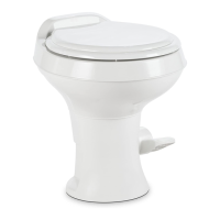
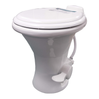
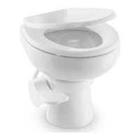
5 Components (g.
1
, page 2)
Ref. Description
A Toilet seat
B Flush ball seal
C Toilet bowl
D Toilet base
E Flush pedal
F Floor ange seal
Ref. Description
G Vacuum breaker cover
H Vacuum breaker
I Water valve
J Floor mounting hardware kit
Refer to complete parts list (available online at
www.dometic.com) for additional information.
6 Installation
Note
Be sure foot pedal, when pressed, touches same at surface on which toilet is installed.
Note
Be sure to follow recommended installation requirements in section 4.2 of this manual.
6.1 Tools required
• pliers or adjustable wrench
• 7/16-in. / 11 mm wrench
6.2 Toilet installation
1. To replace an older toilet, turn off water supply to toilet. Remove and drain water supply line.
Remove toilet hold-down bolts/screws. Remove toilet from oor. Remove and discard old oor
ange seal and hold-down bolts. Verify center of oor ange is at least 10 inches / 254 mm
from back wall (g.
3
A, page 2). Make sure top surface of oor ange is clean and free of any
debris or sealant.
2. If installing a new oor ange, make certain that toilet mounting holes are located at the correct
angle (g.
3
B, page 2). Floor ange must be secured to oor with a minimum of four screws
(8 is preferred). Insert two supplied T-bolts into slots in oor ange (g.
4
, page 2).
Dometic Model 310 Toilet Specifications / Installation