17
CCC Ducted Installation Instructions
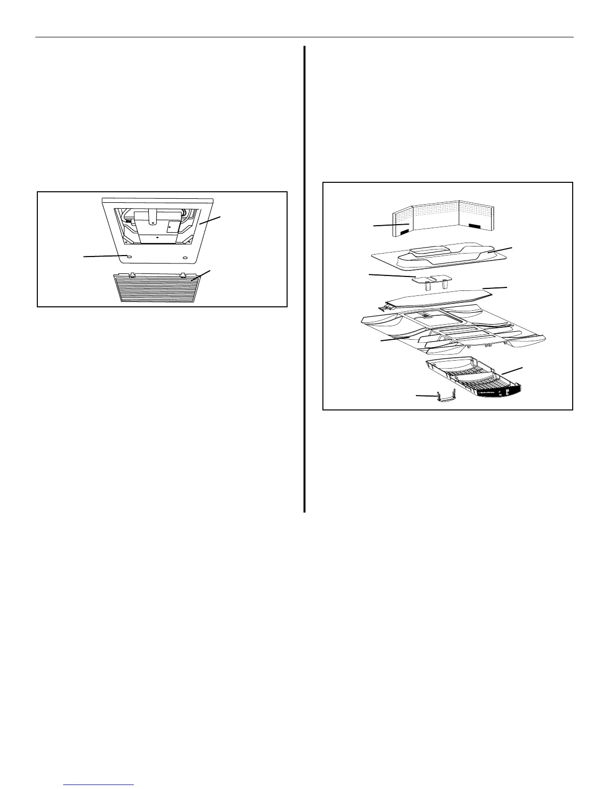
FIG. 19A
Return Air
Cover
Hole
Plugs
Return
Air Grill
Installing unit with 3105007.XXX or 3105935.XXX
Return Air Cover, continued from page 15, column A.
7. Position the electronic control box on the tabs of
the ceiling template. Secure the control box to the
template with 2 blunt self tapping screws. See FIG.
19A.
C. INSTALLATION OF INSIDE DECORATIVE COVER.
1. Remove the return air grill from the return air cover.
2. Place the return air cover up to the ceiling tem-
plate.
3. Install cover to template with #8 x 3/8” pointed
Phillips head screws provided (6 required).
4. Reinstall lter return air grill into return air cover.
Align tabs with mating notches and snap into
place
5. Install two hole plugs into screw holes in back of
return air cover. See FIG. 19A.
6. This completes the installation of the air condi-
tioner/heat pump. We recommend that power
be supplied to the air conditioner/heat pump and
check for proper operation. Refer to Operating
Manual or User's Guide for a description of the air
conditioner/heat pump operation.
Installing unit with 3308120.XXX Genesis Air Filtration
System, continued on page 16, column B.
Installing unit with 3308120.XXX Genesis Air Filtration
System, continued from page 15, column B.
2. Slide the lter from the right side (looking toward
the RV front) over the wires. Make sure the wires
are secured above the lter and are out of its way.
See FIG. 19B.
3. Place grill on return air cover and snap in place. Decal
is on end over circuit board.
4. Place slide handle through slots in grill into the slide
posts. Handle will t in either direction. See FIG. 19B.
5. This completes the installation of the air condi-
tioner/heat pump. We recommend that power
be supplied to the air conditioner/heat pump and
check for proper operation. Refer to Operating
Manual or User's Guide for a description of the air
conditioner/heat pump operation.
M
icro-Therm
Filter
System
F
I
L
T
E
R
R
E
S
E
T
C
L
E
A
N
F
I
L
T
E
R
Return Air
Cover
FIG. 19B
Grill
Foam
Divider
Ceiling
Template
Slider
Filter
Handle