Do you have a question about the Dometic 620525.321 and is the answer not in the manual?
Alert symbol and its meaning regarding potential personal injury.
Definitions of WARNING, CAUTION for hazard levels.
Explanation of moisture condensation and its effect on RV interiors.
Critical warnings for safe and correct installation procedures.
Criteria for selecting the ideal roof placement for the unit.
Steps for creating and reinforcing the roof opening for the AC.
Guidelines and charts for duct sizing and airflow requirements.
Recommended methods for installing the air distribution ductwork.
Electrical specifications for connecting power to the unit.
Advice on selecting the best mounting spot for the control center.
How to route and connect the control cable from the unit.
Using a template to guide the cutting of the ceiling opening.
Installing the divider plate for airflow and sealing.
Steps for installing units with non-center discharge ducting.
Steps for installing units with center discharge ducting.
Connecting 12V DC, sensor, furnace, and EMS wiring.
Connecting the primary AC power source to the unit.
Setting dip switches for system options and zone control.
Performing a system reset after configuration adjustments.
Testing system functions to ensure proper operation.
Electrical schematic for earlier production models.
Electrical schematic for later production models.
| Brand | Dometic |
|---|---|
| Model Number | 620525.321 |
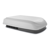
| Product Type | Air Conditioner |
| Cooling Capacity (BTU/h) | 13500 |
| Voltage (VAC) | 115 |
| Frequency (Hz) | 60 |
| Number of Speeds | 3 |
| Installation Type | Rooftop |
| Control Type | Manual |
| Color | White |