6
641515, 641516, 641535, 651515 & 651516 Installation Instructions
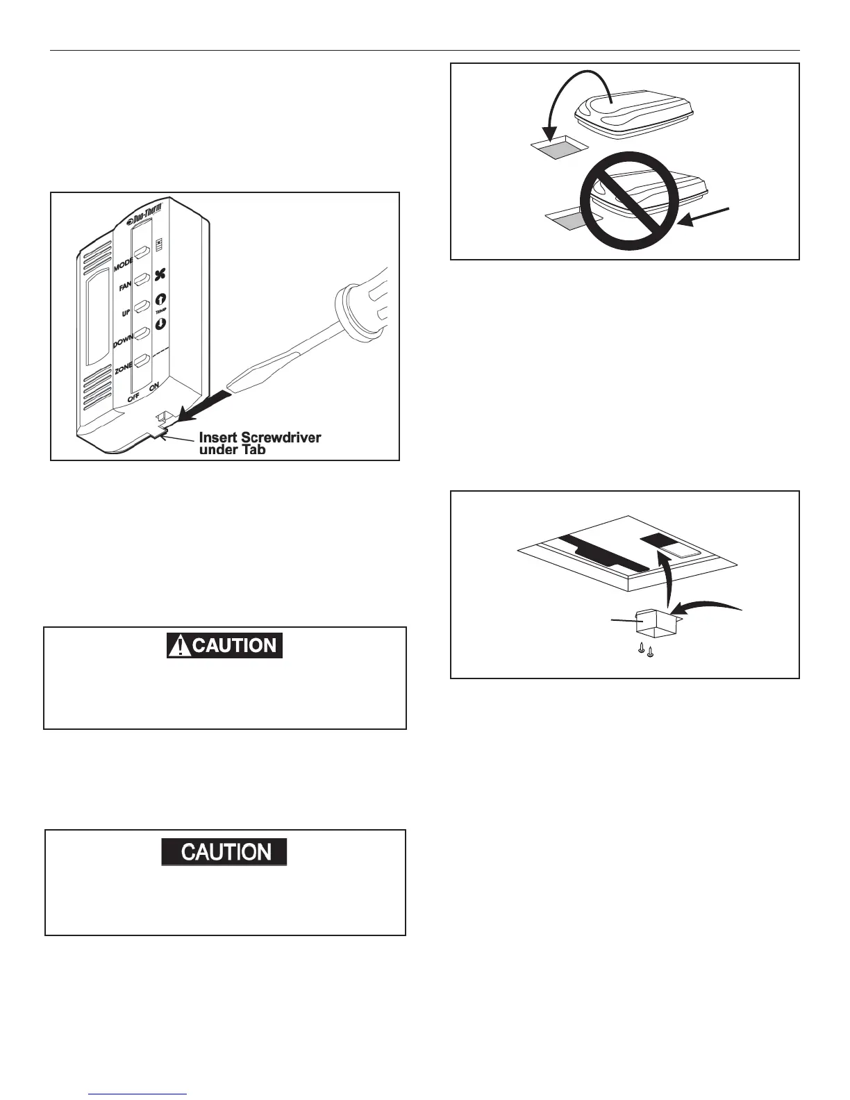
FIG. 7
b. Insert the control cable through the hole in the
base plate and mount the plate to the wall with
two (2) screws provided. Check the alignment
to ensure level installation.
c. Install the control cable RJ-11-6C4P connector
into the back of the Comfort Control Center™
and snap onto the base plate. See FIG. 7.
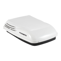
F. Placing Unit On The Roof
This unit weighs approximately 100 pounds.
To prevent back injury, use a mechanical hoist
to place unit on roof.
FIG. 8
FRONT
1. Remove the unit from the carton.
2. Place the unit on the roof.
3. Lift and place the unit over the prepared opening
using the gasket on the unit as a guide. See FIG.
8.
4. Place the 3106615 Air Distribution Box Kit and
3109228 Comfort Control Center
TM
inside the
RV. This box contains mounting hardware for the
unit and will be used inside the RV.
This completes the outside work. Minor adjust-
ments can be done from the inside of the RV if
required.
G. Installing The Unit
1. Remove air box and mounting hardware from
carton. The upper duct is shipped inside the lower
duct which is part of the ceiling template.
2. Remove upper duct from ceiling template and
locate it over blower discharge. See FIG. 9.
Note: Edge without fl ange installs toward REAR of open-
ing.
3. Use two (2) sharp pointed #10 sheet metal screws
to hold duct to base pan. Screw holes are provided
in bottom of base pan for these screws.
4. Check for correct alignment and adjust the unit
as necessary (Roof Gasket centers over 14-1/4"
x 14-1/4" (±1/8") opening).
5. Reach up into return air opening of the unit and pull
the unit electrical cord down for later connection.
6. Measure the ceiling to roof thickness:
a. If distance is 2"-3", remove perforated tabs
from bottom duct only. See FIG. 10.
Do not slide the unit. This may damage the
roof gasket attached to the bottom and may
create a leaky installation.
Rear Of Unit
Upper Discharge
Air Duct
Edge Without
Flange To
Rear Of Unit
FIG. 9
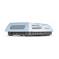
3. Comfort Control Center
TM
Installation
a. Carefully remove the base plate from the
Comfort Control Center
TM
. This may be
accomplished by inserting a small screw-
driver under the tab on the bottom edge of
the front cover and gently prying. See FIG.
7.
 Loading...