6
3. Lower the lateral arm assembly until the shoul-
der’s keys engage the shoulder base’s grooves
at positions (1) and (3). See FIG. 12.
PINCH POINT HAZARD. Keep clear of pivot
area when raising or lowering lateral arm
assembly. Failure to obey this caution could
result in injury.
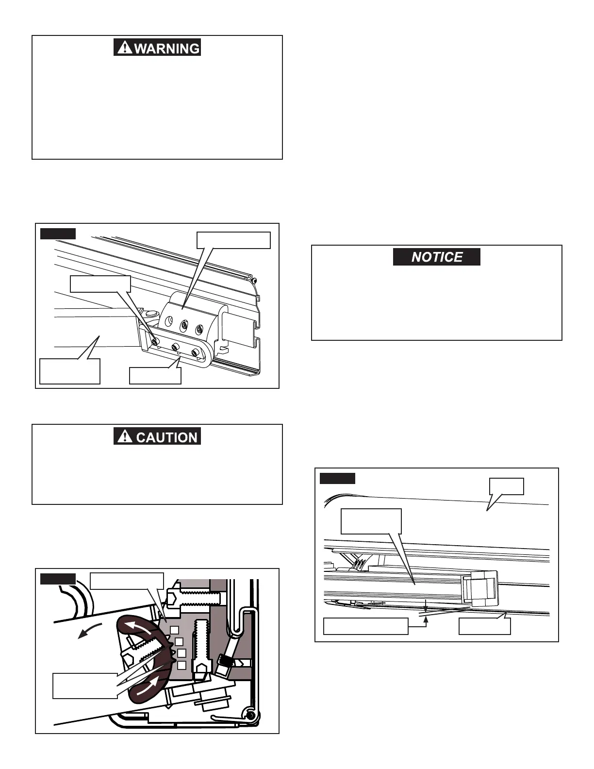
2. Loosen the (3) cap screws (3.5 turns maximum)
clamping the shoulder to the shoulder base on (1)
lateral arm assembly only. See FIG. 11.
IMPACT OR CRUSH HAZARD. Make sure lat-
eral arm assemblies are taped and supported
securely with lead rail before loosening fas-
teners. Otherwise, the lead rail and lateral arm
assemblies could shift or drop quickly and
unexpectedly. Failure to obey this warning
could result in death or serious injury.
FIG. 12
4
3
2
1
Shoulder’s
Keys
Shoulder Base
FIG. 11
Shoulder Base
Shoulder
Lateral Arm
Assembly
Cap Screws
C. Readjust Lateral Arm Assemblies (If
Required)
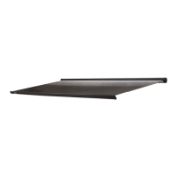
After fabric slope adjustment, verify that cassette awning
will close without interference. If awning will not close
properly, or if lateral arm assembly’s elbow will not clear
back rail, it will need readjustment. See FIG. 13.
Note: The lateral arm assembly’s elbow should just clear
(slightly above) lower lip of back rail without rubbing. Ad-
justing too high may interfere with top, or cause rubbing
on awning fabric.
4. Tighten cap screws to 140 in-lb torque to re-clamp
the shoulder to the shoulder base. See FIG. 11.
5. Repeat steps (2) through (4) for each lateral arm
assembly. Remove tape when done.
FIG. 13
Elbow Clearance
Lateral Arm
Assembly
Top
Back Rail
Do not allow lateral arm assemblies to rub
against lower lip of back rail when closing,
or against awning fabric when in fully opened
position. Failure to obey this notice could
result in property damage.