7
Follow this procedure to readjust lateral arm assembly
clearance:
1. Extend awning far enough to access shoulder
base (approximately 1'). See FIG. 14.
2. Slightly loosen the (2) cap screws (per lateral
arm assembly) clamping the shoulder base to the
shoulder bracket. See FIG. 14 and 15.
Important: Loosen cap screws just enough to re-
lieve clamping pressure on components. Do not back
screws out any farther.
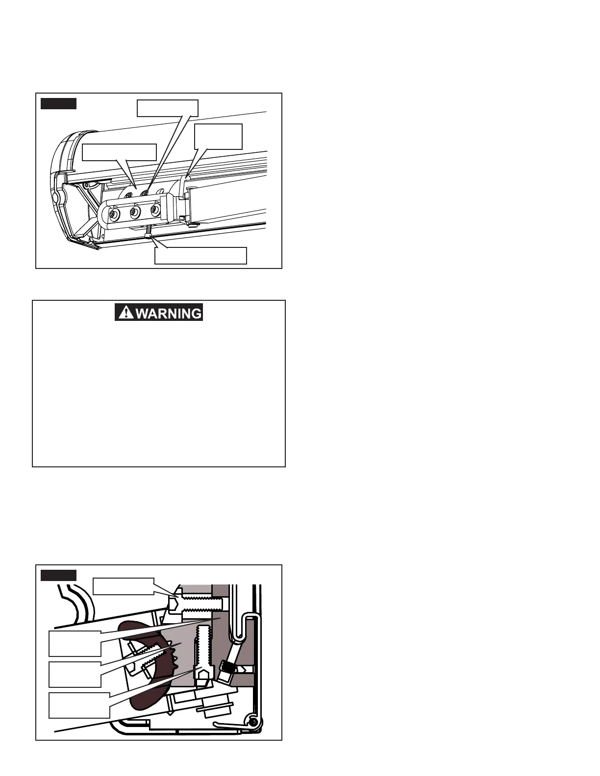
FIG. 14
Shoulder Base
Shoulder
Bracket
Cap Screws
Adjustment Screw
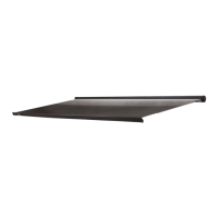
FIG. 15
Shoulder
Base
Shoulder
Bracket
Cap Screws
Adjustment
Screw
IMPACT OR CRUSH HAZARD. Do not com-
pletely remove fasteners, or loosen them so
far that shoulder base will disengage from
shoulder bracket. The lead rail and lateral
arm assemblies could drop quickly and un-
expectedly, or lateral arm assemblies could
extend to the side, beyond awning perimeter
quickly and unexpectedly. Failure to obey this
warning could result in death, serious injury,
or property damage.
3. Readjust lateral arm assembly’s closing height.
See FIG. 14 and 15.
a. Turn adjustment screw in shoulder base IN to
raise or OUT to lower lateral arm assembly.
Note: This will also affect the lead rail height. See “Realign
Lead Rail” section to adjust lead rail alignment.
b. Retract awning until lateral arm assembly’s
elbow meets top and back rail to check for
clearance.
c. Extend awning far enough to access shoul-
der base.
d. Repeat steps (a) through (c) as necessary.
e. When you reach appropriate clearance, tight-
en the (2) cap screws to 140 in-lb torque (per
lateral arm assembly) to clamp the shoulder
base to the shoulder bracket.