2
A&E 8500 & 9000 FRTAA&E 8500 & 9000 FRTA
A&E 8500 & 9000 FRTAA&E 8500 & 9000 FRTA
A&E 8500 & 9000 FRTA
INSTINST
INSTINST
INST
ALLAALLA
ALLAALLA
ALLA
TIONTION
TIONTION
TION
COVERED BY PATENT 4,524,791
This is so that when the entry door or the screen
door is swung out while the awning fabric is extended
low, the door roller or the door edge-guard (instead of
the sharp door corner) makes contact with the under-
side of the fabric.
2.2.
2.2.
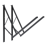
2. Carefully lay the fabric roller tube assembly on "V"
troughs or other well protected surface to prevent fabric
damage. Mount the arms to the top castings by installing
the 1/4-20 x 1/2" hex. cap screws with lock washers
through the arms and into the top castings.
(FIG. 2)(FIG. 2)
(FIG. 2)(FIG. 2)
(FIG. 2).
CAUTION: DO NOT REMOVE the lock end cotter pinCAUTION: DO NOT REMOVE the lock end cotter pin
CAUTION: DO NOT REMOVE the lock end cotter pinCAUTION: DO NOT REMOVE the lock end cotter pin
CAUTION: DO NOT REMOVE the lock end cotter pin
at this time and DO NOT attempt to rotate the Safe-T-at this time and DO NOT attempt to rotate the Safe-T-
at this time and DO NOT attempt to rotate the Safe-T-at this time and DO NOT attempt to rotate the Safe-T-
at this time and DO NOT attempt to rotate the Safe-T-
LockLock
LockLock
Lock
TM TM
TM TM
TM
Lever until installation is complete. (LeverLever until installation is complete. (Lever
Lever until installation is complete. (LeverLever until installation is complete. (Lever
Lever until installation is complete. (Lever
has been pre-set in the roll-up position.) (FIG. 2)has been pre-set in the roll-up position.) (FIG. 2)
has been pre-set in the roll-up position.) (FIG. 2)has been pre-set in the roll-up position.) (FIG. 2)
has been pre-set in the roll-up position.) (FIG. 2)
Position Wheel
Directly over edge
of Door
Wheel Above
Door 1/4" – 3/8"
ENTRYENTRY
ENTRYENTRY
ENTRY
DOORDOOR
DOORDOOR
DOOR
FIG. 1AFIG. 1A
FIG. 1AFIG. 1A
FIG. 1A
DOOR EDGEDOOR EDGE
DOOR EDGEDOOR EDGE
DOOR EDGE
GUARDGUARD
GUARDGUARD
GUARD
SCREENSCREEN
SCREENSCREEN
SCREEN
DOORDOOR
DOORDOOR
DOOR
FIG. 1BFIG. 1B
FIG. 1BFIG. 1B
FIG. 1B
FIG. 2
IMPORTANT: Read ALL of the following steps beforeIMPORTANT: Read ALL of the following steps before
IMPORTANT: Read ALL of the following steps beforeIMPORTANT: Read ALL of the following steps before
IMPORTANT: Read ALL of the following steps before
beginning installation.beginning installation.
beginning installation.beginning installation.
beginning installation.
The Dometic Corporation reserves the right to modify
appearances and specifications without notice.
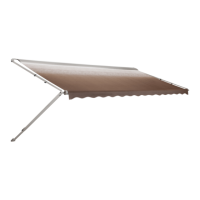
ApplicationApplication
ApplicationApplication
Application
The
A&E RECESSED HARDWARE™A&E RECESSED HARDWARE™
A&E RECESSED HARDWARE™A&E RECESSED HARDWARE™
A&E RECESSED HARDWARE™ is designed and
intended for use and installation into a special pocket built
in the side of motorhomes, mini-motorhomes, 5th wheels
and travel trailers with straight or curved sides. The FRTA
is intended to mount to
standardstandard
standardstandard
standard awing rails mounted on
the outer wall surface of the vehicle.
"
RECESS SPECIFICATIONS:RECESS SPECIFICATIONS:
RECESS SPECIFICATIONS:RECESS SPECIFICATIONS:
RECESS SPECIFICATIONS:
Recess Locations, when built into the coach, must be in
even full foot measurements apart, center-to-center, or left
edge to left edge for the awning to fit and function properly.
Awnings are available in even foot lengths from 7' to 25'.
The
recess size recess size
recess size recess size
recess size must be 6.5" wide x 1.5" deep x 73.75" to
87.25" high.
The
recess baserecess base
recess baserecess base
recess base is the mounting structure for the awning
foot. The vehicle must have adequate strength in this area
to support the awning in transit and in use.
The
recess toprecess top
recess toprecess top
recess top should be within 2"of the awning rail to
allow proper alignment of the fabric and roller tube.
The
top brackettop bracket
top brackettop bracket
top bracket mounts to the area directly above the
recess. The vehicle must have adequate structure here to
support the awning rafters in use.
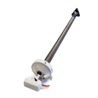
CENTER TENSIONING AND SUPPORTCENTER TENSIONING AND SUPPORT
CENTER TENSIONING AND SUPPORTCENTER TENSIONING AND SUPPORT
CENTER TENSIONING AND SUPPORT
ACCESSORIES:ACCESSORIES:
ACCESSORIES:ACCESSORIES:
ACCESSORIES:
There is an adapter in the hardware parts pack to allow the
A&E Optima Tension Rafter to be used with the A&E
Automatic Center Support and then stowed in transit. The
rafter and support are accessories which may be pur-
chased separately.
Installation of A&E Awnings may at some points, require
three people. Use the following procedure to assure a
properly installed, and properly functioning awning.
1.1.
1.1.
1. Where the A&E Awning is to be mounted above the
entry door, the door roller must be installed on the
exterior side of the door in the extreme upper corner
above the door handle.
(FIG. 1A)(FIG. 1A)
(FIG. 1A)(FIG. 1A)
(FIG. 1A)
In addition, if there is a screen door inside the
regular door, a door edge guard must be installed on
the exterior side of the screen door, in the extreme
upper corner opposite the door hinges.
(FIG. 1B)(FIG. 1B)
(FIG. 1B)(FIG. 1B)
(FIG. 1B)
 Loading...