3
33
33
3. Remove the left end cotter pin (non-locking end)
after after
after after
after
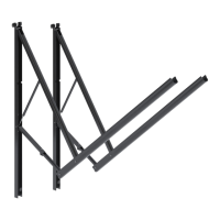
both hardware arms are attachedboth hardware arms are attached
both hardware arms are attachedboth hardware arms are attached
both hardware arms are attached
.
4.4.
4.4.
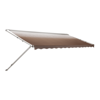
4. Prepare the awning rail to accept the awning roller
cover by selecting the end from which the awning shall
be fed, then widen that end of the rail with a flat
screwdriver. Lift the handle and lower the inner arm to
the ground to support the awning.
(FIG. 3)(FIG. 3)
(FIG. 3)(FIG. 3)
(FIG. 3)
5.5.
5.5.
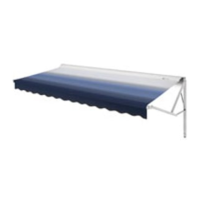
5. With one person grasping each support arm, carefully
lift the entire assembly to an upright position.
Keeping the two arm assemblies
ParallelParallel
ParallelParallel
Parallel to each other
to avoid excessive twisting and possible damage to
assembly, walk the awning back to the end where the
awning rail was prepared.
(FIG. 4)(FIG. 4)
(FIG. 4)(FIG. 4)
(FIG. 4)
A third person is now required to feed the roller cover
into the awning rail while standing on a stepladder,
while the other two walk the entire awning assembly
forward and into the desired position.
(FIG. 4) (FIG. 4)
(FIG. 4) (FIG. 4)
(FIG. 4)
6.6.
6.6.
6.
Installation of Bottom Mounting BracketsInstallation of Bottom Mounting Brackets
Installation of Bottom Mounting BracketsInstallation of Bottom Mounting Brackets
Installation of Bottom Mounting Brackets
Bolt the bottom bracket to the angled mounting plate with
two 1/4-20 x 1/2" cap screws and nylon insert lock nuts.
(FIG. 5)(FIG. 5)
(FIG. 5)(FIG. 5)
(FIG. 5)
Position the bracket to the base of the vehicle pocket and
mark the screw locations. Pre-drill 3/16"dia. holes at 45-
degree angles through the marked locations (7/32"dia. if
drilling into steel).
(FIG. 6)(FIG. 6)
(FIG. 6)(FIG. 6)
(FIG. 6)
Secure the angle bracket with two #14 x 3" hex. head
screws.
(FIG. 6) Do not overtighten(FIG. 6) Do not overtighten
(FIG. 6) Do not overtighten(FIG. 6) Do not overtighten
(FIG. 6) Do not overtighten.
Seal the bolt and screw locations, and all locations where
the angled mounting brackets meet the coach, with clear
silicone to protect against water entry.
(FIG. 7)(FIG. 7)
(FIG. 7)(FIG. 7)
(FIG. 7)
FIG. 5FIG. 5
FIG. 5FIG. 5
FIG. 5
FIG. 6FIG. 6
FIG. 6FIG. 6
FIG. 6
FIG. 7FIG. 7
FIG. 7FIG. 7
FIG. 7
BEFORE
AFTER
ARM
ASSEMBLIES
AWNING
RAIL
FABRIC ROLLER
TUBE ASSEMBLY
FIG. 4FIG. 4
FIG. 4FIG. 4
FIG. 4
FIG. 3FIG. 3
FIG. 3FIG. 3
FIG. 3
 Loading...