4
FIG. 9BFIG. 9B
FIG. 9BFIG. 9B
FIG. 9B
FIG. 9AFIG. 9A
FIG. 9AFIG. 9A
FIG. 9A
MAIN ARM
ASSEMBLY
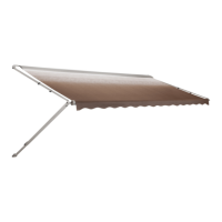
Release the adjustable arm by lifting the handle, and slide
it up to the bottom mounting bracket. Snap the foot of the
adjustable arm into the mounting bracket.
(FIG. 8B)(FIG. 8B)
(FIG. 8B)(FIG. 8B)
(FIG. 8B)
7.7.
7.7.
7.
Installation of Top Mounting Brackets.Installation of Top Mounting Brackets.
Installation of Top Mounting Brackets.Installation of Top Mounting Brackets.
Installation of Top Mounting Brackets.
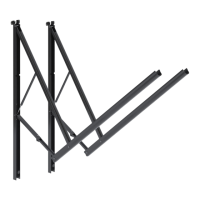
Align the arm squarely in the recess. Insert the rafter top
pivot into the top bracket. Place top bracket in position
against the top of the recess as shown in
FIG. 9A, 9BFIG. 9A, 9B
FIG. 9A, 9BFIG. 9A, 9B
FIG. 9A, 9B, and
aligned directly behind and centered with the main support
arm.
Pull the main support arm away from the vehicle. Mark the
top bracket position and predrill the two holes using a 3/16"
drill bit. (Use 7/32" drill bit if drilling through steel). Install top
bracket with two #14 x 2" hex. hd. screws
(FIG. 9B)(FIG. 9B)
(FIG. 9B)(FIG. 9B)
(FIG. 9B). It is
recommended that clear silcone be used to seal the screw
where it enters the coach.
Repeat for other side.
8.8.
8.8.
8.
Installation of Stop PlugsInstallation of Stop Plugs
Installation of Stop PlugsInstallation of Stop Plugs
Installation of Stop Plugs
CAUTION: This step is essential for the proper func-CAUTION: This step is essential for the proper func-
CAUTION: This step is essential for the proper func-CAUTION: This step is essential for the proper func-
CAUTION: This step is essential for the proper func-
tioning of all A&E Awningstioning of all A&E Awnings
tioning of all A&E Awningstioning of all A&E Awnings
tioning of all A&E Awnings.
With both bottom brackets installed, and both main arms
closed fully against the coach and lowered onto the top
pivot, RAISE THE MAIN ARM UP BY ONE HOLE by lifing
it with the handle. (FIG. 9C)
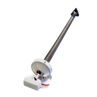
On the front of the adjustable arm, locate the small 3/16"
dia. hole which is closest to the bottom of the main arm
(FIG. 10)(FIG. 10)
(FIG. 10)(FIG. 10)
(FIG. 10). Install aluminum stop plug in this hole by insert-
ing a #10 x 5/8" phillips screw through the stop plug and
through the hole. Secure with a #10 lock nut
(FIG. 10).(FIG. 10).
(FIG. 10).(FIG. 10).
(FIG. 10).
Lower the arm onto the stop plug.
THE MAIN SUPPORT ARM SHOULD NOW COM-THE MAIN SUPPORT ARM SHOULD NOW COM-
THE MAIN SUPPORT ARM SHOULD NOW COM-THE MAIN SUPPORT ARM SHOULD NOW COM-
THE MAIN SUPPORT ARM SHOULD NOW COM-
PLETELY CLEAR THE TOP BRACKET AS IT SWINGSPLETELY CLEAR THE TOP BRACKET AS IT SWINGS
PLETELY CLEAR THE TOP BRACKET AS IT SWINGSPLETELY CLEAR THE TOP BRACKET AS IT SWINGS
PLETELY CLEAR THE TOP BRACKET AS IT SWINGS
TOWARD THE VEHICLE SIDE. (FIG. 9A)TOWARD THE VEHICLE SIDE. (FIG. 9A)
TOWARD THE VEHICLE SIDE. (FIG. 9A)TOWARD THE VEHICLE SIDE. (FIG. 9A)
TOWARD THE VEHICLE SIDE. (FIG. 9A)
Repeat for other side.
FIG. 10FIG. 10
FIG. 10FIG. 10
FIG. 10
MAIN ARM
ALUMINUM
STOP PLUG
#10 x 5/8"
PHILLIPS HD.
SCREW
ADJUSTABLE
ARM
3/16" DIA. HOLE
CLOSEST TO
MAIN ARM
#10 LOCK NUT
LIFT
HANDLE
AJUSTABLE
ARM
FIG.FIG.
FIG.FIG.
FIG.
9C9C
9C9C
9C
FIG. 8BFIG. 8B
FIG. 8BFIG. 8B
FIG. 8B
FIG. 8AFIG. 8A
FIG. 8AFIG. 8A
FIG. 8A
 Loading...