Do you have a question about the Dometic CU401 and is the answer not in the manual?
Explains safety symbols and their meaning for hazard awareness.
Provides guidance on proper use, maintenance, and storage of the manual.
Lists safety precautions and important usage guidelines for operating the appliance.
Describes the function of control knobs and symbols on the appliance.
Explains symbols for burner flame regulation and controls.
Guidance on selecting burners and pan diameter for stability.
Instructions for electronic and manual ignition of hotplate burners.
Introduces oven usage, including initial heating and safety.
Procedures for igniting the oven and regulating its flame with a thermostat.
Introduces grill usage, including ignition and safety warnings.
Instructions for electronic and manual ignition of the grill burner.
Details on regulating the grill flame for different models.
Operation of electric hotplate, spit, and turntable accessories.
Procedures for cleaning the appliance safely and effectively.
Detailed methods for cleaning surfaces and avoiding damage.
Guidance on identifying and addressing abnormal appliance behavior.
Information on overall dimensions and required cavity clearances for installation.
Instructions for safely connecting the gas supply, including warnings.
Details gas types, pressure, and nominal gas consumption rates.
Procedures for connecting gas pipes and checking for leaks.
Information on injector sizes and 12V electric connection.
Warnings about gas leak testing and using naked flames.
Guide for connecting models with 230-240V electric hotplates.
How to secure the appliance and test its operation.
Details on locating test points and understanding the data plate.
Important safety warnings before performing any servicing.
Step-by-step guide for servicing hotplate parts.
Instructions for servicing oven and grill parts.
Procedures for servicing gas controls and ignition systems.
Instructions for removing and refitting the oven door.
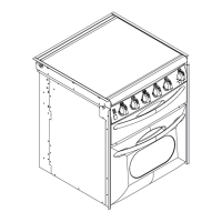
Diagram showing appliance structure or a specific part.
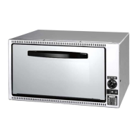
Diagram illustrating a specific component or assembly.
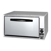
Illustration of another part or assembly of the appliance.
Diagram showing installation clearances and model references.
Technical drawings showing dimensions for CU3xx models.
Technical drawings showing dimensions for CU4xx models.
Technical drawings showing dimensions for FO/PI80xx models.
Technical drawings showing dimensions for PI84xx/PI86xx models.
Technical drawings showing dimensions for MO/VN models.
Diagrams illustrating the fixing and securing of CU appliances.
Diagrams showing installation methods for various CU models.
Diagram for FO311 and PI series model installation.
Diagrams showing screw fitting details for PI models.
Diagrams showing screw fitting details for MO/VN models.
Image of a test point fitting.
Diagram showing a test point location on an appliance.
Images illustrating servicing procedures for components.
| Weight | 21 kg |
|---|---|
| Features | safety features |
| Type | Gas |
| Burners | 2 |
| Material | Stainless steel |
| Gas type | Butane or propane |