28
EN
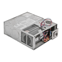
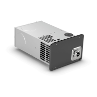
Furnaces
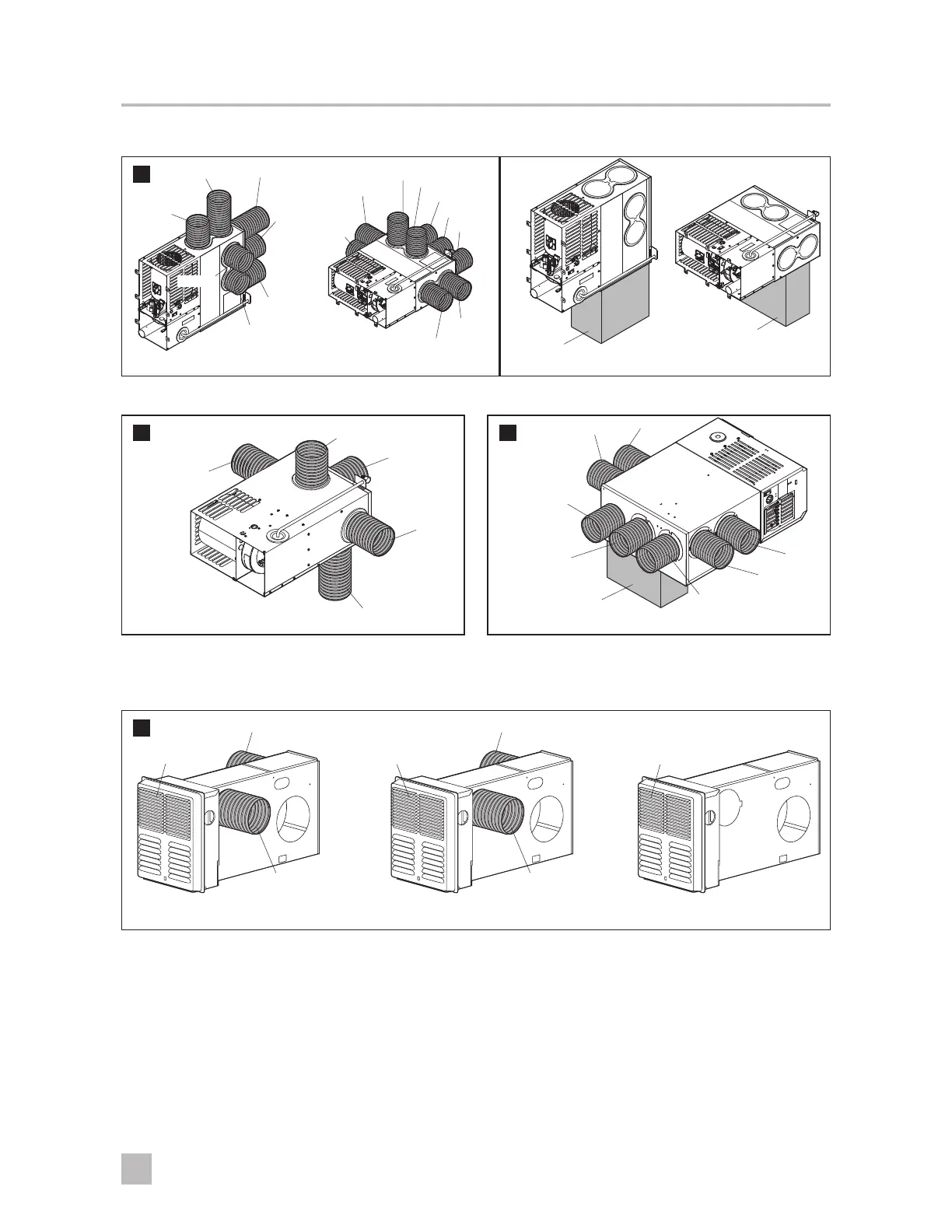
Identify the Duct Locations
Vertical Duct View
Horizontal
Duct View
11
Duct 1
Duct 3
Duct 5
Duct 8
Duct 9
Duct 5
Duct 4
Duct 3
Duct 1
Duct 4
Duct 5
Duct 7
Duct 6
Vertical
Discharge
Horizontal
Discharge
Duct 9
Duct 8
Duct 2
(AFM/DFM, AFL/DFL)
12
(AFS/DFS)
Duct 1
Duct 2
Duct 3
Duct 5
Duct 4
13
(85, 89, 2-Stage)
Bottom Discharge
Duct 1
Duct 7
Duct 6
Duct 5
Duct 4
Duct 2
Duct 3
I
For additional ducting requirements or specific air-discharge information, consult the installation
instructions for the furnace.
14
Duct 1 Duct 1
Front
Discharge
(closed)
Front
Discharge
Front
Discharge
Duct 2 Duct 2
(7912, 7916, 7920
with front discharge)
(8012, 7912, 7916, 7920
front discharge only)
(8012, 7912, 7916, 7920
with front discharge)
Check the Return Air
Similar to the ducting requirements for the furnace, a minimum number of square inches is also required for the
return airflow. To determine if the return air passageways are contributing to, or causing an operational issue for
the furnace, perform the following checks:
➤ Make sure the air passageways are clean and free of obstructions.
➤ Remove any air filters in the passageway.
➤ Confirm the return air passageway meets the minimum square inches required for the furnace.
 Loading...