19
INSTALLATION
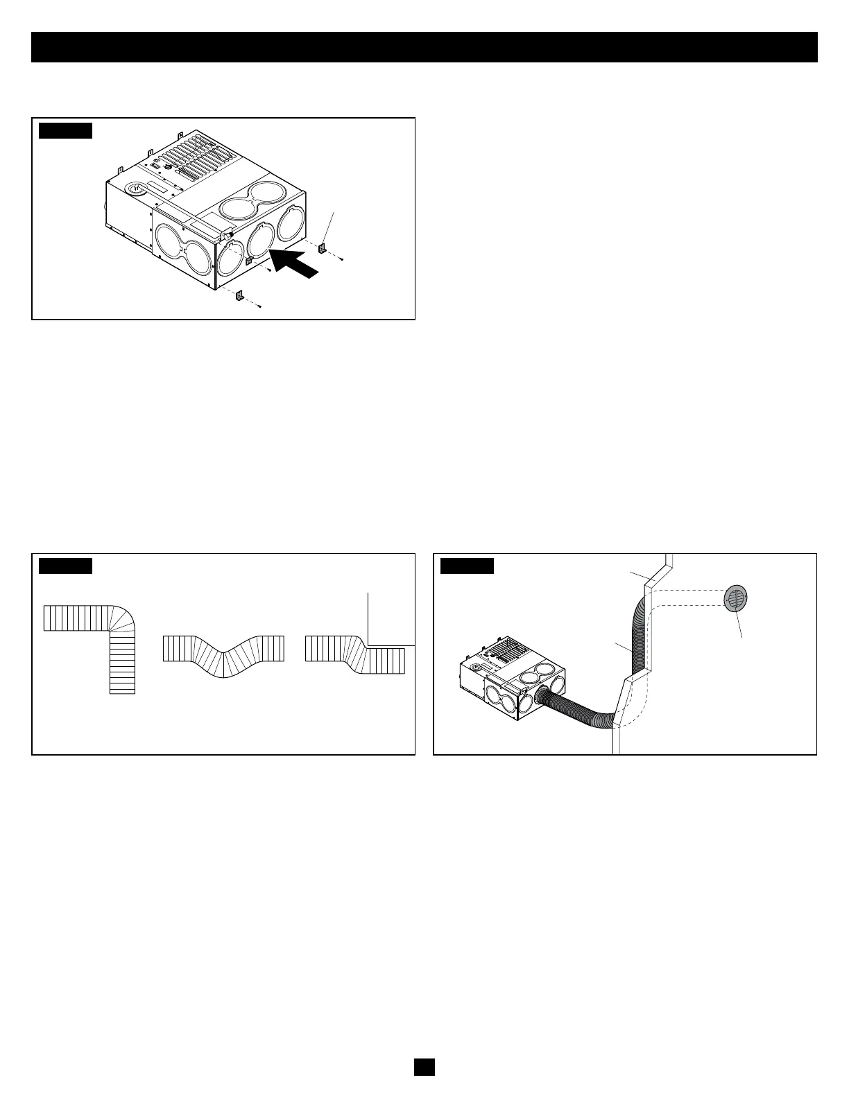
D. Installing The Mounting Brackets
.
STEP1
Mounting
Bracket
• Make sure the mounting surface on the RV is flat and the
Furnace is positioned evenly (front-to-back, side-to-side).
• Fasten the two mounting brackets (provided) to the casing
by placing the brackets over any two of the three holes
at the rear of the Furnace. Secure using two #8-18x1/2"
screws (provided).
• Secure the Furnace mounting brackets to the RV using
screws (not provided).
Mounting brackets can be attached to the Furnace casing
by removing an existing casing screw, ONLY with prior
approval from Dometic. When securing the Furnace, it
MUST be accessible and easily removed for service.
E. Running the Ductwork
STEP1
Not Recommended
• Stretch out all of the ducts and run them directly to the
outlets. Keep the number of angles to a minimum and
avoid sharp bends, deep sags, or crushed ducts, as shown.
• Attach and secure the 4" flexible duct to the adapter(s).
STEP2
Ducting
Heat Register
RV Wall
• Run duct(s) to the desired location(s) within the RV.
• Secure the ducting to the register(s).
If the burner cycles ON and OFF at the high-temperature
limit, it may be due to a restriction or bend in the ductwork.
Add extra ducting to correct this condition.
• Adjust the Furnace to the proper temperature rise aer
installation of the Furnace and ducting is complete. The
Furnace is tested to the temperature rise specified on the
rating plate.
• If checking the temperature rise is not possible, measure the airflow
at each register. Airflow should meet or exceed the measurements
in the “Air Discharge Requirements” on page 11.
• Adjust the ducting installation to obtain an airflow rate total
from all living area vents (in CFM) of the Furnace, as specified
in the “Air Discharge Requirements” on page 11.
• If readings are below the table values, improve the airflow
by adding ducts or reducing/eliminating system restrictions.
Reference the “Air Discharge Configuration Examples” on
page 10 for guidance.