20
INSTALLATION
F. Connecting The Gas
FIRE OR EXPLOSION HAZ ARD. Failure to obey the following warnings could result in property damage, serious
injury, or death:
• Install gas connections in compliance with the applicable supplemental directives listed in this manual. Refer to
“C. Supplemental Directives” on page 2.
• NEVER use an open flame to check for gas leaks. Use a commercially available soap solution made specifically for the
detection of leaks to check all connections, as specified in these instructions.
• Should the gas supply fail to shut off or if overheating occurs, shut off the gas valve to the Furnace before shutting off the
electrical supply.
• Do NOT put sealing compound on flare fittings.
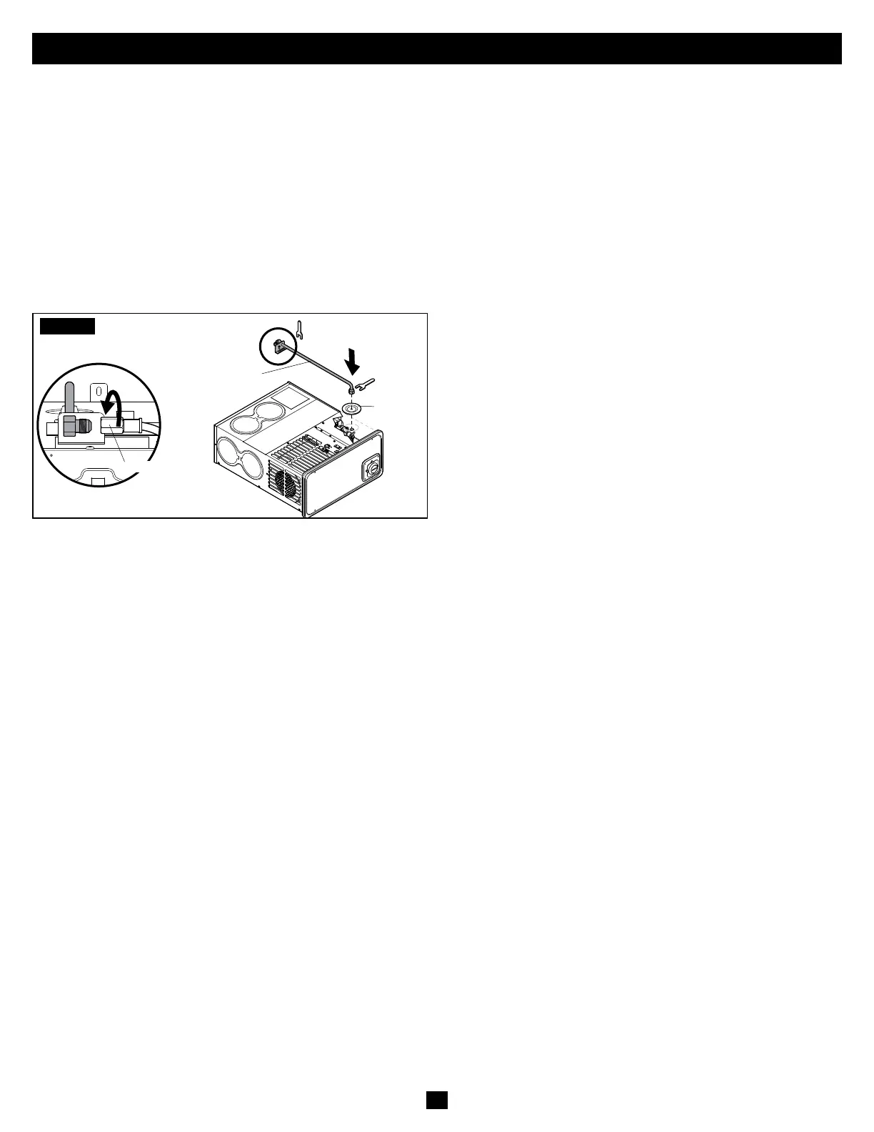
FIG.1
Extended
Manifold
(Rear)
Gas Connection
Grommet
Plug
An extended manifold is used in this example; however,
the use of tubing or other variations to connect the gas is
acceptable.
• Treat all male pipe threads, other than flare fittings, with a
sealing compound resistant to a chemical reaction with LP
gas.
• Remove the grommet plug from the Furnace and install on
the gas line.
• Insert the gas line through the hole in the top of the casing.
• Connect the gas line to the fitting located on the valve. If
the Furnace is supplied with an extended manifold,
connect the gas line at the rear of the Furnace.
• Reinstall the grommet plug on the casing, as it is a required
air seal. DO NOT CUT.
• Use two wrenches to hold the valve and flare nut, and
tighten the flare nut over the gas line.
• Torque the fitting to 20–22 . lbs. Do NOT twist the valve
out of position when tightening the gas line.
For DFLA35 and DFLA40 models only, a gas conversion kit
is included with your Furnace. To convert the Furnace gas
type, proceed to “G. Converting The Furnace Gas Type” on
page 21.
LP Gas Pressure Test
Read BEFORE proceeding:
• Test all piping systems BEFORE connecting the
Furnace.
• Disconnect the Furnace and any individual shut-off
valves from the gas supply piping system when
pressure testing the system at pressures of more than
1/2" PSI.
• If local codes allow the use of a flexible gas appliance
connector, do NOT use a connector which has
previously serviced another gas appliance.
• For gas conversions only, a 1/8" NPT plug is provided
upstream of the gas connections for checking the gas
pressure.
• Perform an air pressure test on the piping system. The test
must maintain an air pressure of a least 6" of mercury or
3 PSI for at least 10 minutes.
• Adjust the piping system to maintain the minimum gas
supply pressure listed on the rating plate, when all
appliances are in operation.
• Test gas connections for leakage with a commercially
available soap solution made specifically for the detection
of leaks.
 Loading...