8
EN
Installation Magnetic-Drive Centrifugal Pump
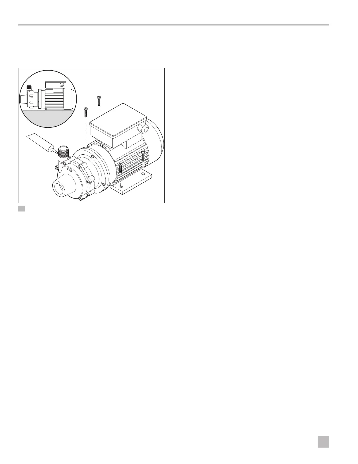
5.3 Mounting the Pump
Use the following instructions to securely mount the
pump in the desired location.
q
e
w
r
4 Mounting With Vertical Discharge Orientation (P030 Shown)
q
Sealant
e
Foot
w
Motor
r
Pump Head
1. Place the pump motor in the desired location and
mark the position of the mounting holes.
2. Drill holes for the mounting screws.
3. If the pump was packaged with plastic shipping
shims, place the shims under the motor feet.
4. Tighten the screws to secure the pump into position.
5. Use an appropriate pipe sealant or tape on the
threads and other piping connections.
6. Tighten all connections, using appropriate tools for
the selected piping materials.
5.4 Connecting the Piping
Use the following guidelines for connecting the piping.
• Place the piping with independent support near the
pump to eliminate any strain on the pump casing.
• A strainer on the inlet pipe should be used to remove
debris before the liquid enters the pump.
• Position the piping on the suction side of the pump
in a straight and short configuration to minimize pipe
friction.
• Keep bends and valves at least ten pipe diameters
away from the suction and discharge.
• Install the suction piping to be level or sloping slightly
upward toward the pump. To prevent air pockets, the
suction line should not have any high spots.
• The suction line should be at least as large as the
suction inlet port or one pipe size larger so that it
does not affect the NPSHa. Do not reduce the suction
line size.
• A check valve and control valve (if used) should be
installed on the discharge line. The check valve helps
prevent the pump from water hammer damage. This
is particularly important when the static discharge
head is high. The control valve is used for regulating
flow.
• Isolation valves on the suction and discharge lines
can be used to make the pump accessible for
maintenance.
• If flexible hose is preferred, use a reinforced hose
rated for the proper temperature, pressure and
chemical resistance against the fluid being pumped.
• Use an appropriate pipe sealant or tape on the
threads and other piping connections.
• The suction valve must be completely open to avoid
restricting the suction flow.
• A flush system in the piping can be installed to allow
the pump to be flushed before it is removed from
service.
I
P048, P075, P100, P137, P150, and P200 pump
models are provided with a provision for a
customer-installed 1/4 in. (6 mm) drain in the
impeller housing. For the best performance, ensure
the pump piping is sized appropriately for the flow
rate.