12
EN
Maintenance Magnetic-Drive Centrifugal Pump
q
y
w
e
r t
u
h
g
j
d
f
sao
i
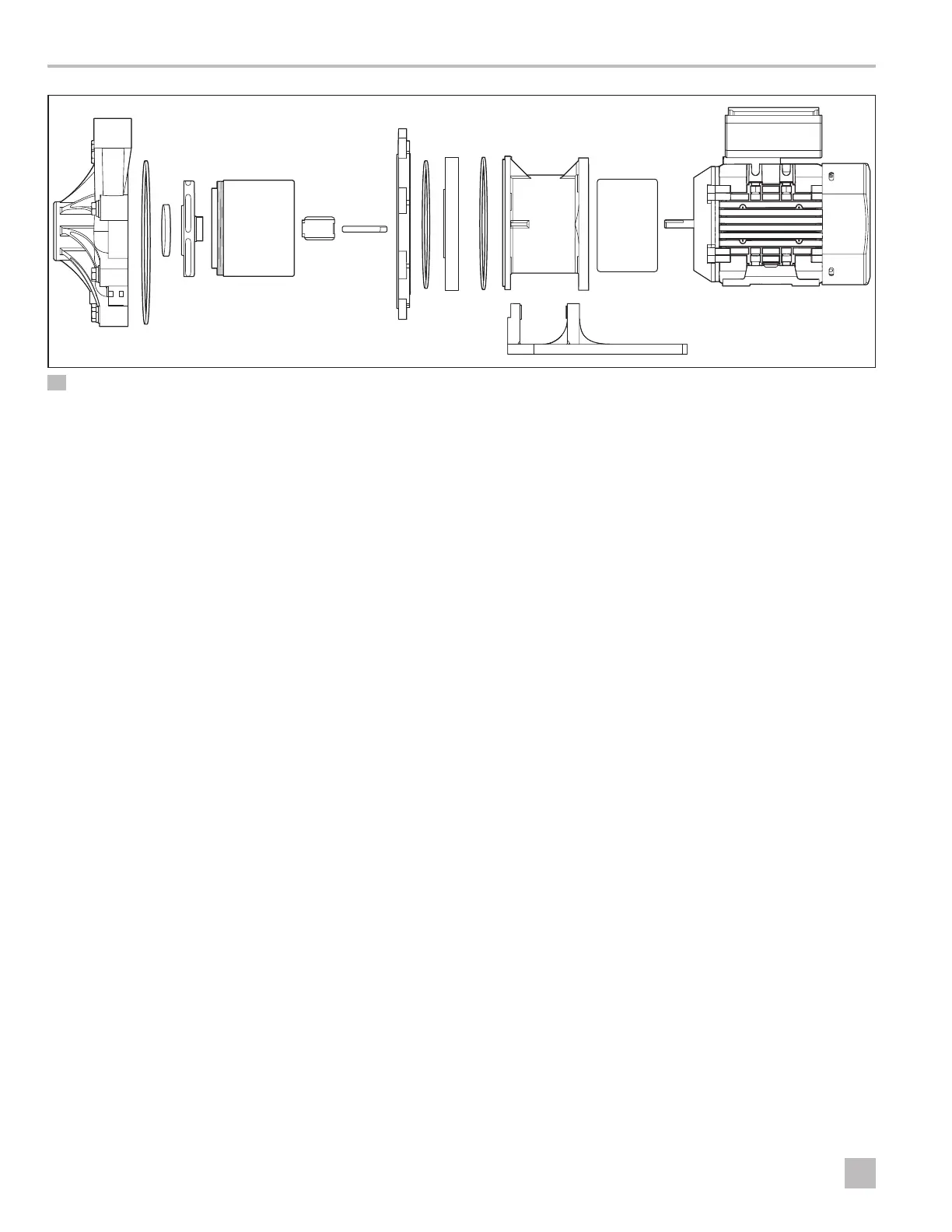
7 Exploded View - P137, P150, P200
q
Pump Housing
t
Impeller Drive Assembly
o
Barrier O-Ring
f
Outer Drive Magnet
w
Housing O-Ring
y
Impeller Bushing
a
Clamp Ring (not
included on P200)
g
Motor Sha
h
Motor
e
Impeller Thrust Ring
u
Impeller Sha
s
Clamp O-Ring
j
Foot (not included
on P200)
r
Impeller Assembly
i
Motor Barrier
d
Motor Adapter
1. Shut down the pump, lock out the motor from the
power supply, flush the pump, and drain all fluid.
Refer to “7.2 Flushing and Draining the Pump” on
page 10.
2. For small pumps 2 hp (1.5 kW) or less, place the
pump and motor in an upright position on the fan
end of the motor or securely clamp the foot to a
workbench. For larger pumps with 3 hp (2.2 kW) or
greater, place the pump securely on the floor with the
pump head facing up.
3. Remove the screws or bolts and lock-washers (if
present) securing the pump head to the motor
adapter/barrier. Use tools appropriate for the
fasteners installed. (The P030 motor adapter includes
the barrier, while other models have a separate motor
barrier and motor adapter.)
4. Firmly hold one side (either the pump head or the
motor, depending on the size and weight of the
model) and pull straight out to disengage the pump
head and motor. If the pump head has the optional
o-ring seal, make sure the o-ring remains on the
motor adapter.
5. Place the pump head on a workbench with the
housing facing up.
6. Remove the screws or bolts on the outside of the
pump housing. The number of housing fasteners
depends on the pump model.
7. Firmly hold the pump housing and pull straight up to
remove it from the pump head.
8. Remove the impeller thrust ring, the impeller
assembly, the impeller drive assembly, and the
impeller bushing.
9. Remove the impeller sha. On the P030, the impeller
sha is attached to the motor adapter. For all other
models, the impeller sha is attached to the motor
barrier.
10. Remove the motor barrier and barrier o-ring (if
present) from the motor adapter. If necessary, gently
tap on the backside of the motor barrier with a so
wooden or plastic rod to dislodge it. (This step does
not apply to the P030.)
11. Remove the clamp ring and clamp o-ring from the
motor adapter. (This step does not apply to the
P030.)
I
Nuts may become bonded to the studs over time.
Tightening the nuts before removal ensures the
studs do not back out of the pump head.