26
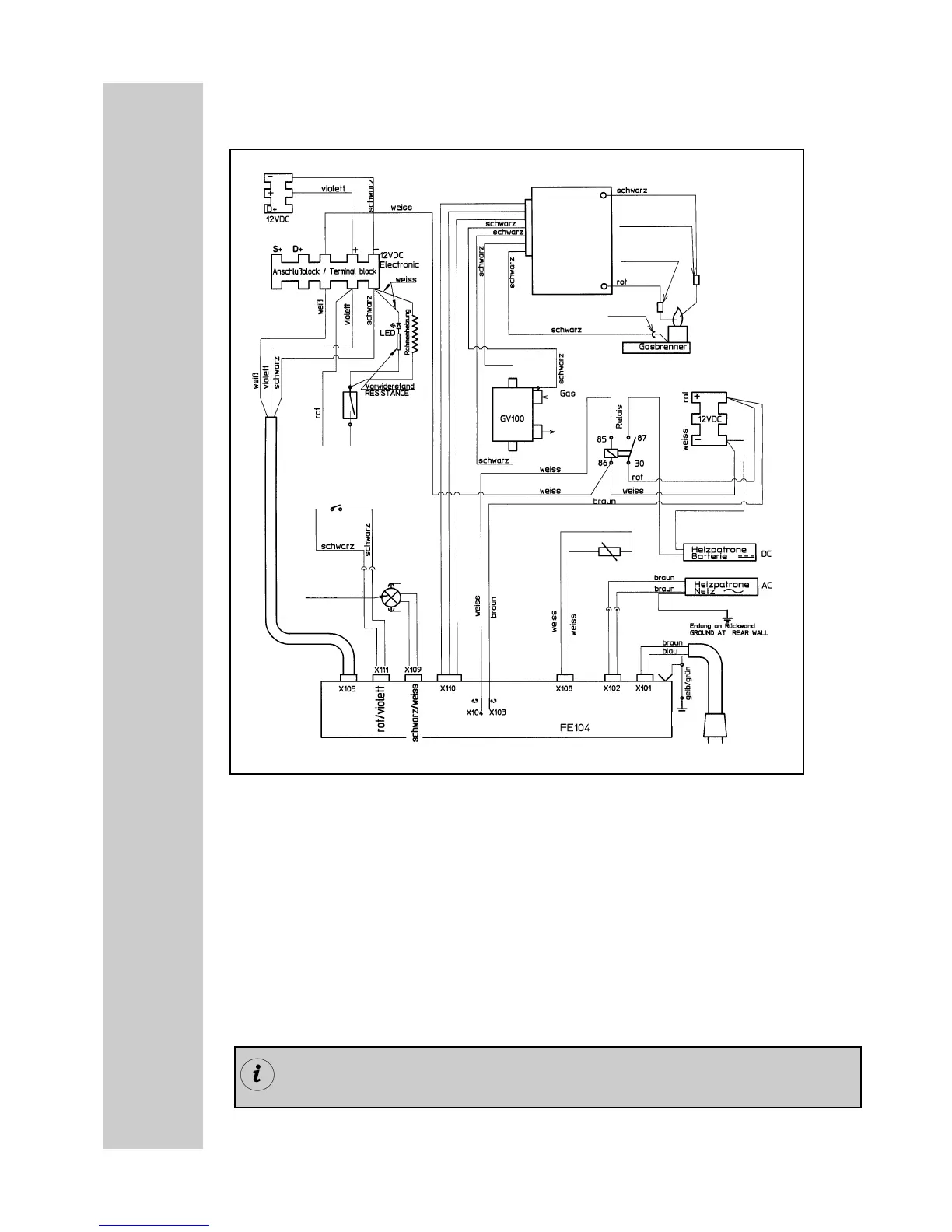
Wiring diagram
Wiring diagram for RM 76x1 L / RM 78x1 L
6.9.6
Connections:
A = Ground heating element DC
B = Plus heating element DC
C = Ground electronics
D = Plus electronics
Colours:
schwarz = black
violett = violet
braun = brown
weiss = white
grün = green
gelb = yellow
rot = red
A
B
C
D
permanently connection DC
Burner
Control
Device
ignition unit
Ground
terminal block heating element DC
Gas
Valve
temp. sensor
heating element DC
heating element AC
Switch
Frame
Heating
ionisation
electrode
ignition
plug
gas burner
Ground
mains
connection
Reed contacts
(sensor switching)
lighting DC
Power Module
For operation, it is compulsory to provide the device with a permanent 12V
DC connection at terminals C/D (permanent voltage supply for the functio-
nal electronics).

 Loading...