B
Bryan BrightAug 19, 2025
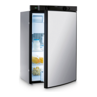
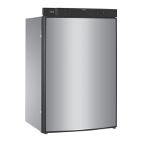
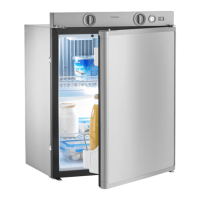
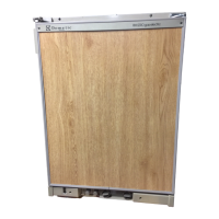
Why is my Dometic RM 8505 not cooling sufficiently?
- WWalter BentonAug 19, 2025
There are several reasons why your Dometic Refrigerator might not be cooling well enough: * The ventilation to the unit might be inadequate. Ensure that the ventilation grilles are not covered. * The thermostat setting could be too low. Try setting the thermostat to a higher level. * The condenser may be heavily frosted. Check that the refrigerator door closes properly. * Too much warm food might have been stored inside recently. Allow warm food to cool down before storage. * The appliance may not have been running long enough. Check whether the cooling compartment works after approximately 4 - 5 hours. * Ambient temperatures could be too high. Regularly remove ventilation grilles.