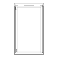
7.8 CROSSOVER TUBE
The crossover tube is located at the top of the flue tube
and is attached with a screw. It must be properly
attached or flame outage could occur. If the balanced
flue tube is too close to the opening of the crossover
tube, it can also cause flame outage or difficulty in
lighting.
7.9 FLUE TUBE
The flue tube is a component of the cooling unit. It must
be cleaned periodically, at least once a year. To clean,
remove crossover tube and flue baffle, then cover the
burner and clean by using a flue brush. If the flue tube
becomes coated with scale or residue from combustion
of LP gas, the efficiency of gas operation decreases.
NOTE: After cleaning be sure to reinstall the flue baffle
and crossover tube.
7.10 ORIFICE
The orifice is a small brass fitting that has a ruby
membrane that is laser beam drilled and is mounted on
the gas line just prior to the burner. The orifice should
be cleaned periodically, at least once a year, by using
an alcohol based solvent and allowing to air dry. Never
use a drill bit or jet tip cleaner to clean any orifice as
these devices will damage the factory machined part
and create a potentially dangerous condition. The
correct orifice for the
RM2150,
RM2190
and RM2201 is
Size F. NOTE: Always use the proper orifice. Never use
a larger orifice as this could cause a lack of cooling
problem.
SECTION 8
WIRING
8.1 EXTERNAL WIRING
A. 120
Volts AC Connection
(RM2201):
The refrigera-
tor is equipped with a three prong (grounded) plug
for protection against shock hazards and should be
plugged directly into a properly grounded three
prong receptacle. DO NOT cut or remove the
grounding prong from this plug.
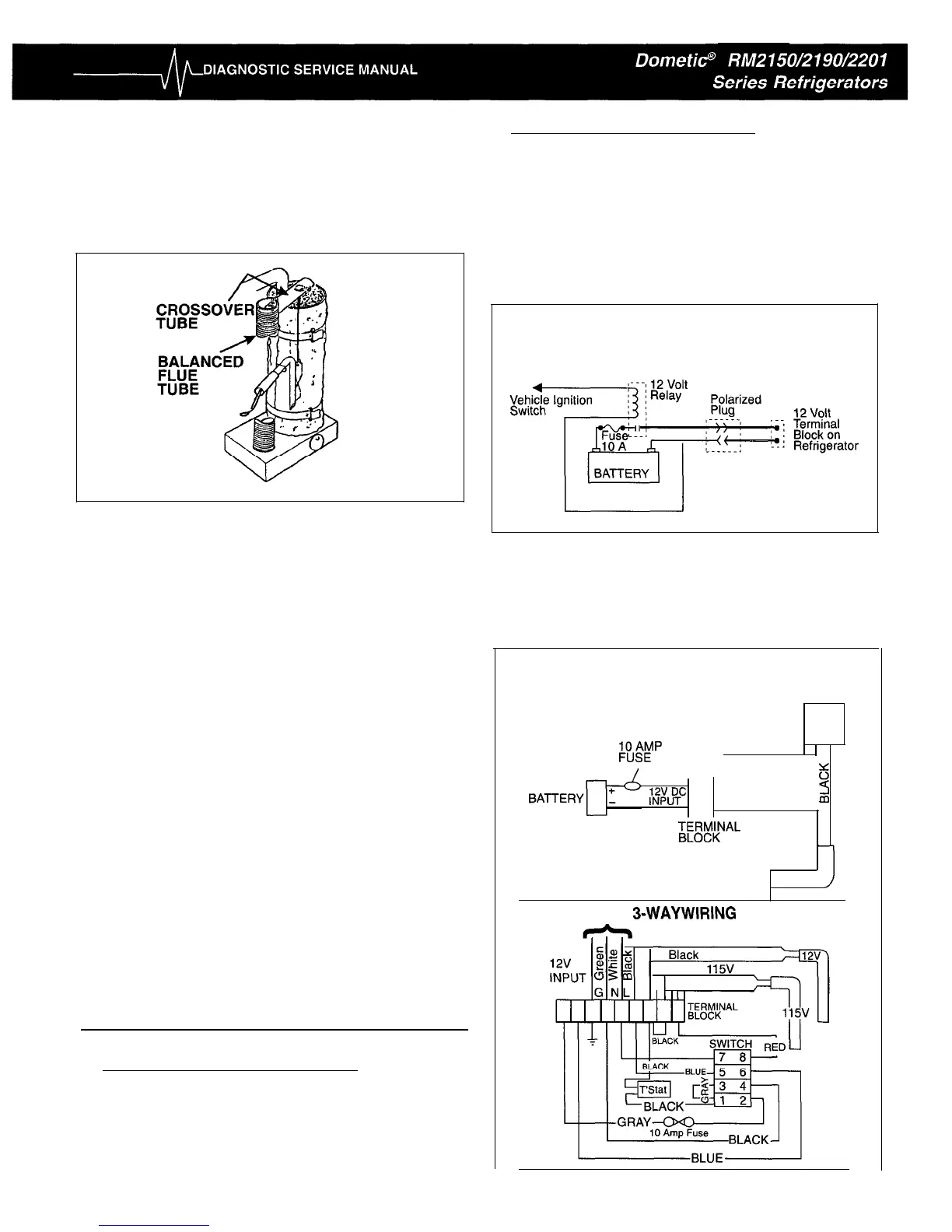
B. 12 Volt DC Connection for Heater: This connection
is made to the terminal block. The refrigerator must
be connected to the battery circuit with two wires of
adequate capacity to avoid voltage drop. The wire
gauge should be 14 AWG.
Do not use the body or chassis of the vehicle as a
substitute for either of the two conductors. No other
electrical equipment or lighting should be connected to
the refrigerator circuit.
TYPICAL WIRING DIAGRAM
12 VOLT SYSTEM
8.2 INTERNAL WIRING
Check all wires and the connectors to ensure a proper
and tight connection. Also verify the refrigerator is wired
per the wiring diagram for the model you are working
on.
TYPICAL
2-WAY
(12V/GAS)
WIRING DIAGRAM
12v
SWITCH
:ousAEMp
BLACK
I
/!u”Tc
3
BLACK
d
TBFI%?AL
HEATING
ELEMENT_
12v
TYPICAL
3-WAYWIRING
DIAGRAM
HEATING ELEMENTS
9
 Loading...