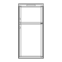
Fig. 4
2 nd
The dimensions shown in
the Table
below will give you
adequate space for service and proper installation. See
Fig. 5.
8.
Gas connection
Hook up to the gas supply line accomplished at the
manual gasshutoff valve, which is furnished with a3/8”
SAE (UNF 5/8”
-
18) male flare connection. All com-
pleted connections should be checked for leaks with a
non-corrosive leak detector. (See Fig. 6)
WARNING
DO NOT USE A FLAME TO CHECK
FOR GAS LEAKS.
Fig. 5
The gas supply system must incorporate a pressure
regulator to maintain a supply pressure of not more than
11 inches water column.
LP GAS
CYLINDER
REGULATOR
REFRIGERATOR
VIEW FROM ABOVE
Refrigerator
model
Overall
Installation
Recess
Distance between
dimensions
dimensions
dimensions
top of condenser
and top of
Height
Width Depth
Height Width
Depth
Height Width
Depth
A B
C
h
W
d
H W
D
refrigerator
e
inch 30-318 21-11116 22-l/16 29-9116 20-l 14 20-316 29-314 20-l 12 21-318 l-114
RM2310
mm 771 551 560 751 514 517 756 521 542 32
-4-