RUC5(x)08X, RUC6(x)08X, RUC8(x)08X Installation
17
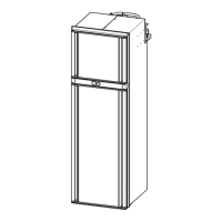
➤ Install an air baffle (fig. 9 5) above the compressor unit to prevent the heat from accumulating in the vehicle.
➤ Make cut outs in the wall for the air inlet and outlet vents. Observe the required dimensions specified in the
installation manual for the LS ventilation grille.
– Position of the air inlet vent: It must be possible to install the ventilation grille so that the lower edge of
the ventilation grille is at least 250 mm from the compressor shelf (fig. 9 1).
– Position of the air outlet vent (rear venting): It must be possible to install the ventilation grille so that
the bottom edge of the ventilation grille is not below the compressor shelf.
Note: Ensure that the bottom edge of the ventilation grille is as close as possible to the compressor shelf
for optimum service access.
No. in
fig. 9
Description
1 Maximum height for the top edge of the ventilation grille
(250 mm below the compressor shelf)
2 LS300 ventilation grille (accessories)
3a Air outlet vent
3b Air inlet vent
4 Minimum height for the bottom edge of the ventilation grille
(equal to the height of the compressor shelf)
5 Air baffle