The Dometic Turbo Direct Expansion (DX) Air Conditioning System is designed to provide cooling for marine applications. This installation manual outlines the proper procedures for setting up the unit, emphasizing safety, optimal performance, and longevity.
Function Description:
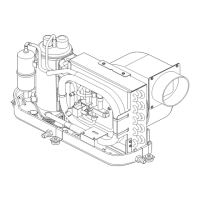
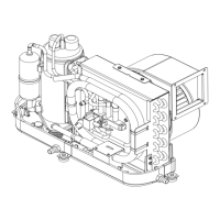
The Dometic Turbo DX AC system is a self-contained air conditioning unit that uses a direct expansion refrigeration cycle to cool the air. It draws in cabin air, cools it over an evaporator coil, and then discharges the conditioned air back into the living spaces. A separate seawater system is used to cool the condenser coil, rejecting heat overboard. The system includes a blower for air circulation, a compressor, and a control system for operation. It is designed to be installed in a low, flat, level surface within a locker, under a bunk, or a dinette seat, ensuring it is sealed from direct access to bilge and/or engine room vapors.
Important Technical Specifications:
The manual provides minimum duct and grill sizes for various Turbo Model Capacities, ranging from 6K to 16K BTU.
- Duct Diameter:
- 6K: 4 inches (102 mm)
- 8K: 5 inches (127 mm)
- 10K & 12K: 6 inches (152 mm)
- 14K & 16K: 7 inches (178 mm)
- Minimum Duct Area:
- 6K: 12.6 sq in (81 sq cm)
- 8K: 19.6 sq in (126 sq cm)
- 10K & 12K: 28.3 sq in (183 sq cm)
- 14K & 16K: 38.5 sq in (248 sq cm)
- Minimum Return Air (R/A) Grill Area:
- 6K: 64 sq in (413 sq cm)
- 8K: 80 sq in (516 sq cm)
- 10K: 100 sq in (645 sq cm)
- 12K: 130 sq in (839 sq cm)
- 14K: 144 sq in (929 sq cm)
- 16K: 160 sq in (1032 sq cm)
- Minimum Supply Air (S/A) Grill Area:
- 6K: 32 sq in (206 sq cm)
- 8K: 48 sq in (310 sq cm)
- 10K: 60 sq in (387 sq cm)
- 12K: 70 sq in (452 sq cm)
- 14K: 76 sq in (490 sq cm)
- 16K: 80 sq in (516 sq cm)
- Condensate Drain: The unit features a 1/2" (12.7mm) NPT PVC hose barb connection for the condensate drain, requiring a 5/8" (15.9mm) I.D. reinforced hose.
- Seawater System: Requires 5/8" (15.9mm) reinforced marine grade hose for connections to the condenser coil.
- Electrical: Requires a minimum of 12 AWG boat cable for power supply. Each A/C unit needs its own dedicated circuit breaker, sized according to the data plate label. If a pump relay panel (PRP) is used for multiple A/C units sharing a seawater pump, the PRP requires its own dedicated circuit breaker (20 amp max). All metal fittings in contact with seawater must be bonded to the vessel's bonding system.
Usage Features:
- Blower Rotation: The blower can be rotated to direct airflow optimally through the ducting. This is achieved by loosening an adjustment screw on the blower mount ring, rotating the blower to the desired position, and then tightening the screw.
- Air Distribution: Supply air grills should be installed as high as possible with louvers directed upward for uniform air distribution. Return air grills should be installed low and close to the A/C unit to ensure direct, uninterrupted airflow to the evaporator.
- Air Filtration: Air filters are essential to remove airborne particulates and keep the evaporator coil clean. One filter must be installed per unit, either on the A/C unit itself (in front of the evaporator coil) or on the return air grill.
- Condensate Management: The condensate drain hose must be routed downward to a sealed condensate or shower sump pump, ensuring gravity flow and preventing dangerous fumes from entering living quarters.
- Seawater System: The seawater scoop intake should be installed as far below the waterline and as close to the keel as possible, facing forward, to ensure continuous water supply, especially in rough seas. A seacock shut-off valve and a seawater strainer are mandatory to protect the pump from foreign matter. The pump must be mounted at least one foot below the waterline.
- Ducting: Ducting should be run as straight, smooth, and taut as possible, minimizing 90° bends (which can reduce airflow by 25%). All ducting must be insulated in high heat load areas and protected from damage. It must not be routed through engine rooms or areas exposed to dangerous vapors.
Maintenance Features:
- Air Filter Cleaning: Air filters must be cleaned regularly as per instructions in the Owner's Control Manual to maintain system performance and air quality.
- Seawater Strainer: The seawater strainer requires periodic access for cleaning to prevent pump damage and maintain water flow.
- Hose Connections: All hose connections in the seawater system should be double-clamped with stainless steel hose clamps and Teflon tape on threaded connections to prevent leaks.
- Electrical Connections: All electrical connections should be made with ring or captive fork terminals. Butt connections on pump wires should be tightly crimped and heat-shrunk.
- Bonding System: Regular checks of the vessel's bonding system are crucial to prevent corrosion due to stray electrical current, especially for all metallic parts in contact with seawater. Failure to properly ground and bond the system will void the warranty.
- Wiring Diagram: The wiring diagram is located in the electrical box of the unit for easy reference during troubleshooting or servicing. Dometic can provide copies if the original is damaged, requiring the unit part number, serial number, and wiring diagram number.