Fixed Way
6
FIG. 11
Install 2 Screws In Tabs
Duct Adapter Screw
Holes Must Line Up
If Necessary Rotate
1/2 A Turn.
Fit Duct Adapter
Inside Duct
If bolts are left loose there may not be an ad-
equate roof seal or if over tightened, damage
may occur to the unit base or ceiling template.
Tighten to torque specications listed in this
manual.
5.
EVENLY TIGHTEN MOUNTING BOLTS TO A
TORQUE OF 4.5 TO 5.6 NM (Newton Meters).
This will compress the roof gasket to approxi-
mately 13 mm. The bolts are self locking so
further tightening is not necessary. See FIG.
10.
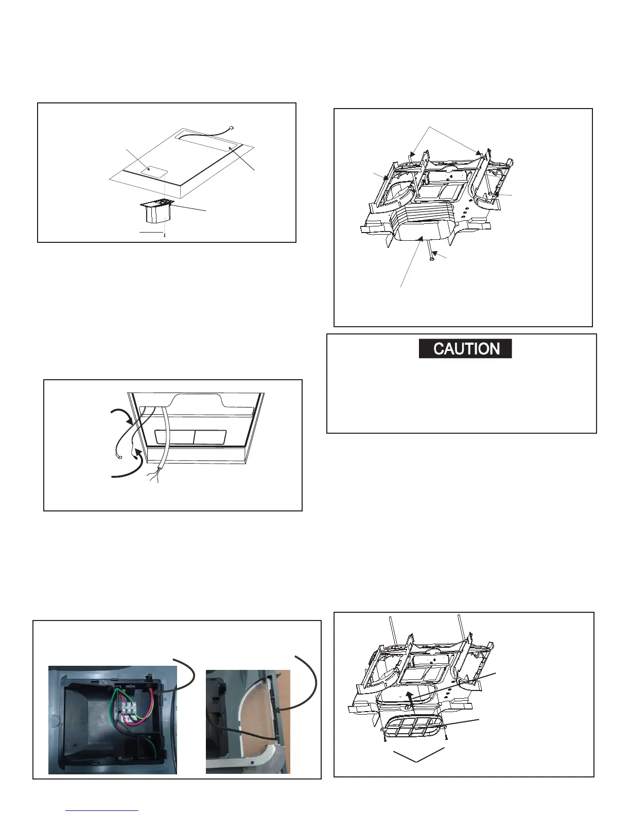
6. Template/Duct adapter
a. Pull duct down through the template open-
ing.
b. Cut the duct 13 mm to 25 mm below the tem-
plate opening. See FIG. 10.
c. Align the template duct adapter with the tem-
plate duct hole making sure the screw holes
line up (if not, rotate 1/2 turn). Insert template
duct adapter into duct. Leave one loop of wire
below the duct adapter groove. Do not insert
adapter tabs inside the duct.
d. Snap duct adapter into template and install 2
screws through the duct adapter tabs into the
ceiling template. See FIG. 11.
Return Air
Opening
Discharge
Opening
Remove Liner
From Foam
Tape
Front
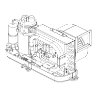
FIG. 7
Screw
FIG. 10
Start 3
Mounting
Bolts By
Hand
Trim Duct 13 mm To
25 mm Below Ceiling
Template
Ceiling
frame
Do not Disturb
the position of
Mounting Bolts
Mounting Bolt
3. Base Pan Duct Adapter
a. Remove the liner from the foam tape and posi-
tion on the base so screw hole and air openings
are aligned. Place ange of duct on right hand
side when facing front. See FIG. 7.
b. Install # 10 screw to help hold the duct adapter
to base pan if desired.
4. Ceiling template installation
Note: The large center hole in the ceiling template goes
to the rear. See FIG. 10.
c.
FIG. 8
Fasten Power Cable as
per
Connect To
a. Reach up into the return air opening and pull the
unit electrical wires down for later connection.
b. Connect the AC power lead and the AC power supply
See FIG. 8.
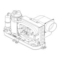
Display Board
Air Distribution Box
Connect To
Power cable and sensor wiring
FIG. 9
The Air Sensor
The Customer Power
Cable Fixed Way
FIG. 9
FIG. 9.
cable together within connection housing
Connect the air sensor to the right hand side of the mou-
nting frame in the special clips. Pull the outer plastic cov-
ering of the wire back to enable the wire to clip in place.
The outer wiring cover will then hold the wire in place.
air sensor
2 in the front
1 in the back
down then.
Pull the ducting
Front
 Loading...