Mounting the camera and transmitter VT50WiFi
12
5.2 Control elements
6 Mounting the camera and transmitter
6.1 Tools required (fig. 3, page 4)
For installation and assembly you will need the following tools:
• Drill head set (1)
• Drill (2)
• Screwdriver (3)
• Set of ring or open-ended spanners (4)
• Tape measure (5)
• Hammer (6)
• Centre punch (7)
To establish and test the electrical connection, the following tools are required:
• Diode test lamp (8) or voltmeter (9)
• Crimping tool (10)
• Insulating tape (11)
• Cable bushing sleeves (optional)
To secure the camera, transmitter and the cable, you may require additional screws, cable
binders and double-sided tape.
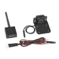
No. in
fig. 2, page 3
Meaning
1 Antenna connection
2 Camera connection
3 Red cable (DC INPUT): Connection to the positive terminal (+) of the
power supply
4 Black cable (GND): Connection to the negative terminal (–) of the
power supply or earth terminal
5 Operating display; lights up as soon as voltage is applied
VT50WiFi-IO-16s.book Seite 12 Freitag, 30. Juni 2017 11:04 11
 Loading...