Dominator Smart Pro, Smart & Secure Instruction Manual9
10. Safety Beam Kit
White
W / G
W / G
White
WARNING! The Opener must be tted with Safety Beams if:
• the closing force at the bottom edge of the door exceeds 400N (40kg) and/or;
• the opener has a smart device tted to operate the door, when not in line-of-sight.
CAUTION! The Safety Beam must be installed and connected
before the travel limits are set.
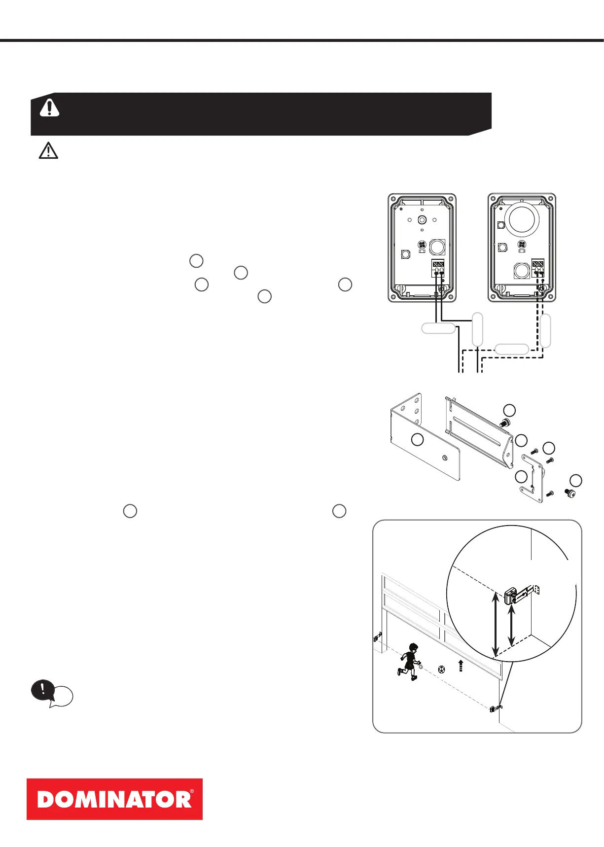
10.1 Wiring the 2 Wire PE Beams
a. Ensure to disconnect power to the opener before opening cover
to connect the 2 Wire PE as per wiring diagram.
b. Ret cover when nished.
10.2 Assemble the Mounting Bracket
a. Attach the PE 2000TS Bracket
1
to the Safety Beam Transmitter
(TX) using four (4) M3 x 5 Taptite screws
4
.
b. Connect the mounting bracket
3
to the adjustment bracket
2
with two (2) of the M5 x 10 Pan Head Screws
5
.
c. Repeat steps (a) and (b) to assemble the Safety Beam Receiver
(RX).
d. Mount the receiver on the side of the doorway in shade and the
transmitter on the other side in line with the receiver. The mounting
surface should be rigid. Afx with a minimum of four (4) screws
(not supplied).
4
1
5
2
3
5
Right side
bracket
65mm
100mm
TX
Sun or Shade
10.3 Mounting the Bracket
The transmitter and receiver need to be placed in line of sight, with
the beam 100mm above the ground level (as per AS/NZS 60335-
2-95:2020). This can be achieved by ensuring the bottom of the
receiver and transmitter are 65mm above ground level. They should
also be placed as close as possible to the door opening with the
receiver (RX) in shade and the transmitter (TX) in sun or shade.
Assembling Flush Mounting Kit (for minimum sideroom applications)
a. Attached the transmitter (TX) and receiver (RX) to the two (2)
PEB4-W1 Bracket
1
with the four (4) M3 x 8 Taptite screws “P”
4
.
b. Ensure to take note of the ATA recommendation in step (d) above
and x the TX and RX to the wall or rigid surface using the two (2)
6.9 x 25 plastic wall plugs (if wall) and two (2) M6 x 25 self tapping
screws.
10.4 Aligning the Transmitter and Receiver
a. Power up the opener with the safety beams connected.
b. The opener beam alignment feature can be used to align beams
via the beeper and main light as a guide;
(i) bright = aligned
(i) dull and Beeper sound = not aligned or blocked.
When the beams are aligned, continue with Section 12 Setting Limits.
If the lights does not dim and the beeper does not sound
when an object blocks the beam then the beam is not
being detected by the opener. - check the PE beam
wiring and alignment.
tip