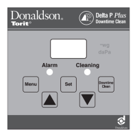
Delta P Plus Control
13
Electrical installation, service, or maintenance work must be performed by a qualied electrician and comply with all
applicable national and local codes.
This equipment may start or stop unexpectedly from a remote location.
Turn power off and lock out all power before performing service or maintenance work.
The appropriate wiring schematic and electrical rating must be used. See collector’s rating plate for required voltage.
Do not install in classied hazardous atmospheres without an enclosure rated for the application.
Electrical Wiring
The Delta P Plus Control is factory set for 115-V. To operate at 230-V, the jumper settings on the printed
circuit board must be changed. See Optional Settings.
1. Choose a location near the collector that permits access to the keypad for adjustments and observation of the pressure drop.
If possible, mount the control indoors.
2. Mount the control enclosure using four self-drilling, self-tapping screws.
Use vibration isolators in high vibration areas.
3. Connect the output contacts to the correrct contact terminals of the pulse control time per the supplied electircal drawing.
These connections will start/stop the cleaning cycle.
4. Wire the auxiliary alarm circuit, if desired. This relay output can be used to activate visual or audible alarms provided by
others. If not wired, the alarm LED light on the control panel will be the only indication of a fault condition.
Use proper grounding and handling procedures to prevent permanent damage to this device. Handle the
printed circuit board by the edges only. Do not touch the socketed E2PROM pins.
5. Wire all remaining auxiliary connections at this time. See the Optional Settings for a list of these options.
6. Thirty-ve feet of plastic tubing is supplied with the control and must be cut in two sections. Connect one section of tubing from
the control enclosure’s high-pressure port to the pressure tap on the dirty-air plenum. Connect the remaining section of tubing
from the control enclosure’s low-pressure port to the pressure tap on the clean-air plenum. Additional tubing can be ordered
from your representative.
7. Apply power to the control. Set the high- and low-pressure setpoints to start and stop the cleaning process. Set the alarm
setpoint to activate the alarm display. See Control Calibration.


 To Next Page