2 6-104402 X2
2000e & 2000eM Keypad Installation & Programming
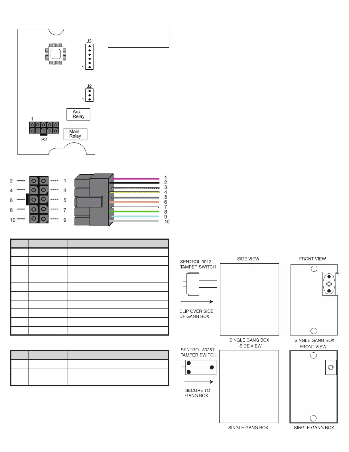
Circuit Board Diagram
Main Wire Harness (P2)
Pin Wire Color Description
1 Red V+ (Keypad Power)
2 Black V- (Keypad Power)
3 White/Black Wiegand Data 0/Secured Series Data
4 White/Yellow Wiegand Data 1/Secured Series Data
5 Brown Request to Exit (REX)/LED1
6 White/Orange Loop Common
7 White Door Position Switch Input
8 Green Main Relay Normally Open
9 Blue Main Relay Common
10 Gray Main Relay Normally Closed
Auxiliary Relay Wire Harness (J2)
Pin Wire Color Description
1 Green Aux Relay Normally Open
2 Blue Aux Relay Common
3 Gray Aux Relay Normally Closed
UL Requirements
The 2000e/2000eM keypad is a UL Listed access control unit. This
section contains information regarding the requirements necessary to
meet UL compliance.
Wiring methods shall be in accordance with the National Electrical
Code (ANSI/NFPA70), local codes, and the authorities having
jurisdiction.
All wires and cables used must be a minimum of 22 AWG, stranded
and shielded UL Listed and/or recognized wire suitable for the
application. In addition, input and output cables that extend from the
unit must be shielded, twisted pair. Ground the shield only at one end,
usually the circuit end.
All interconnecting devices (ie. door contacts, REX, locking devices,
alarm devices, doorbell, etc.) must be UL Listed.
A UL Listed access control power limited power supply, capable of 4
hours standby, must be used to power the keypad.
A minimum of three user codes must be programmed for controlling
access.
The following Wiegand card formats were not evaluated by UL: 28-bit,
29-bit, 30-bit, 31-bit, 32-bit or 36-bit (formats 2-8 from wiegand format
chart. UL did evaluate the 26-bit card format (format 1).
8-Bit Burst Mode was not evaluated by UL.
Installing a Tamper Switch
To meet UL requirements, a UL Listed tamper switch must be
installed in a UL Listed single-gang box used for mounting the
keypad. The tamper switch must activate if the keypad is removed
from the box and must disconnect power from the lock. The lock
must be a fail-secure device, meaning the lock remains locked
when power is removed.
In addition, once the tamper device is activated, it must be
confi gured so that it can only be reset from within the protected
area. Only a Sentrol 3012 or Sentrol 3025T tamper switch can be
used. The diagrams below show the suggested mounting location
for each device.
Note: J3 is for use
only with the 2000-8EX
Output Module.