6 6-104402 X2
2000e & 2000eM Keypad Installation & Programming
Programming Keypad Parameters
(Default settings are in bold)
Command/Action Keys to Enter/Details
Change Keypad Parameters
32 # parameter # value # ✱ ✱
Parameter Value
0 – Duress Output Duration 1 – 255 Seconds (default = 5)
1 – Panic Output Duration* 1 – 255 Seconds (default = 5)
2 – Error Lockout Threshold 1 – 50 Attempts (default = 3)
3 – Error Lockout Duration 1 – 255 Seconds (default = 10)
4 – Auto-Entry Count 2 – 10 Digits (default = 4)
7 – Auto-Entry Keypress
Timeout
2 – 15 Seconds (default = 2)
10 – Wiegand Format 1 – 8 (default = 1, 26-Bit)
11 – Wiegand Pulse Width 1 – 255 (default = 8, 160μS)
12 – Wiegand Interpulse
Spacing
1 – 255 (default = 32, 640μS)
Note: Refer to the Wiegand Format Chart for parameter 8.
Change Wiegand Parameters
34 # parameter # value # ✱ ✱
Parameter Value
0 – Wiegand Site ID Refer to Wiegand Format Chart
1 – Wiegand Group ID Refer to Wiegand Format Chart
Note: The default setting for both settings is 0.
*Note: The Panic Output is activated by pressing the ✱ and # keys
at the same time. This is used in case of emergency to activate an
auxiliary alarm device, such as a siren, that is used to indicate an
emergency condition only. This output should not be used to gain
access. All access control functionality should be programmed and
remain separate from the Panic Output functionality.
Resetting the Keypad
Note: This does not reset the keypad operating mode.
Command/Action Keys to Enter/Details
Reset Defaults Only
40 # 00000 # 00000 # ✱ ✱
Reset Entire Keypad
46 # 00000 # 00000 # ✱ ✱
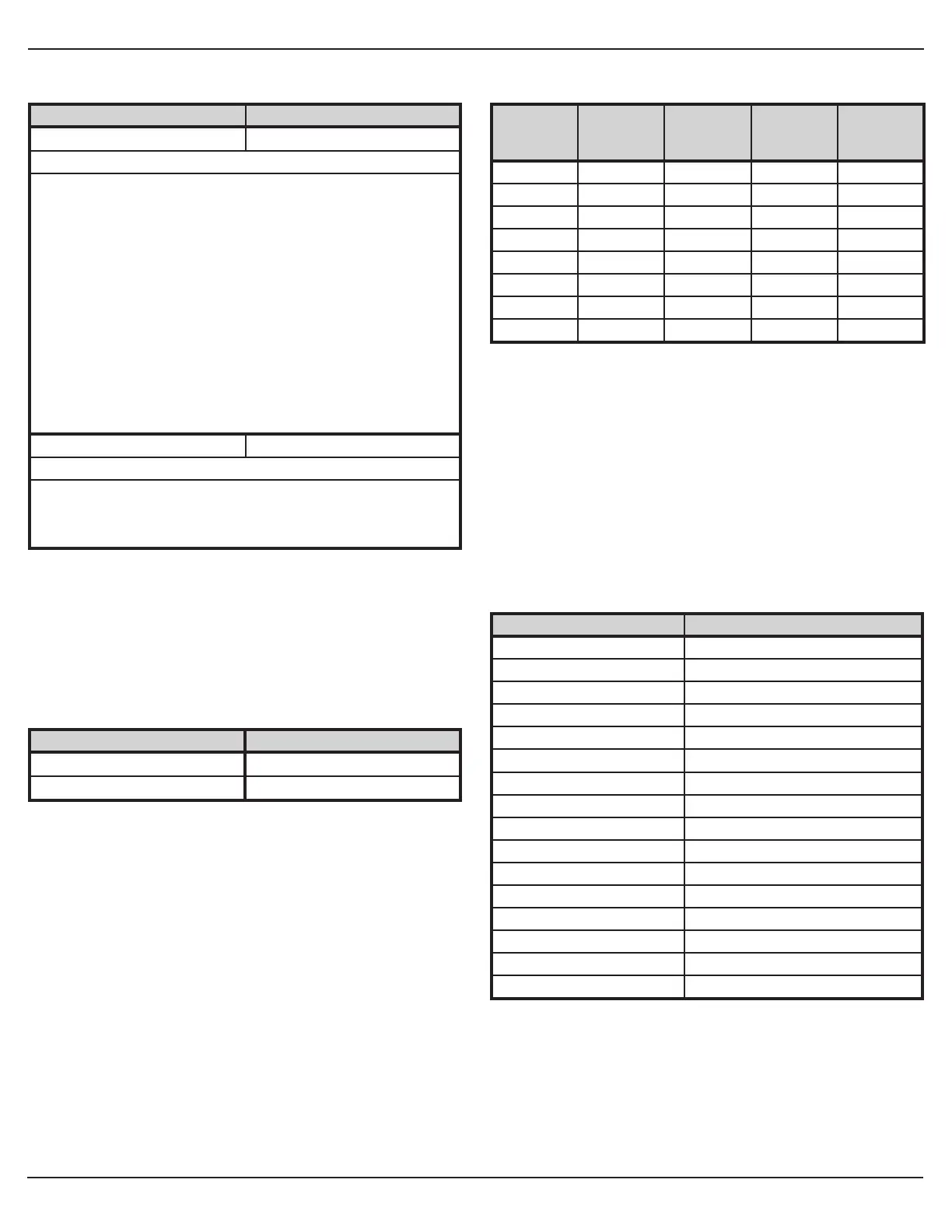
Wiegand Format Chart
The keypad supports the following Wiegand formats (parameter 10).
Format
Value
Wiegand
Format
Largest
PIN Value
Largest
Site Value
Largest
Group
Value
1 26 bit 65535 255 N/A
2 28 bit 32767 255 N/A
3 29 bit 524287 255 N/A
4 30 bit 65535 255 15
5 31 bit 65535 255 31
6 32 bit 8191 2047 63
7 36 bit 999999 1023 N/A
8 29 bit 524287 255 N/A
Wiegand Data
When the keypad is confi gured in Wiegand mode, the keypad data is
sent as a complete Wiegand data packet, as though you presented a
card.
For example, when programming a user into an Door Control Module,
you must program the user as though you were programming a card.
After entering the command to program a card user, enter the code
on the 2000e/eM keypad to send the data to the controller.
Please refer to the Wiegand Interface Module instructions 6-065700,
the HubMax II Instructions 6-065034 and the Hub MiniMax II
instructions 6-055037 for complete details.
LED/Sounder Indications
Indicator Description
Steady Red* Door Locked
Steady Green* Door Unlocked (timed or latched)
Yellow Flashing Slowly Program Mode
Solid Yellow Program Error or Error Lockout
Alternating Red/Green Awaiting 2nd PIN of Two-Part User
LED's Cycling Left to Right Over Voltage Warning
LED's Cycling Right to Left Under Voltage Warning
3 Rapid Beeps Invalid Code
Pair of Double Beeps User Lockout Activated
Single Double Beep User Lockout Canceled
1 Long Beep, 1 Short Beep Access Denied, User Disabled
1 Long Beep, 3 Short Beeps Access Denied, User Lockout
1 Long Beep, 5 Short Beeps Access Denied, Code Mismatch
6 Quick Beeps Toggle Mode Activated
Sounder ¼ sec on, ¼ sec off Audio Alert 1
Beep Every 2 seconds Audio Alert 2
*Note: The Red/Green LED descriptions above are for Standalone
and Secured Series Mode only. The operation of these LED’s in
Wiegand Mode is determined by the LED control wire (brown) and
how it is confi gured. The LED control is confi gured using keypad
Options 19, 20, 21 and 22, which are programmed with Command 30.
 Loading...