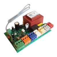
ELECTRICAL CONNECTIONS 0,75 KW
Port Function Wire colour
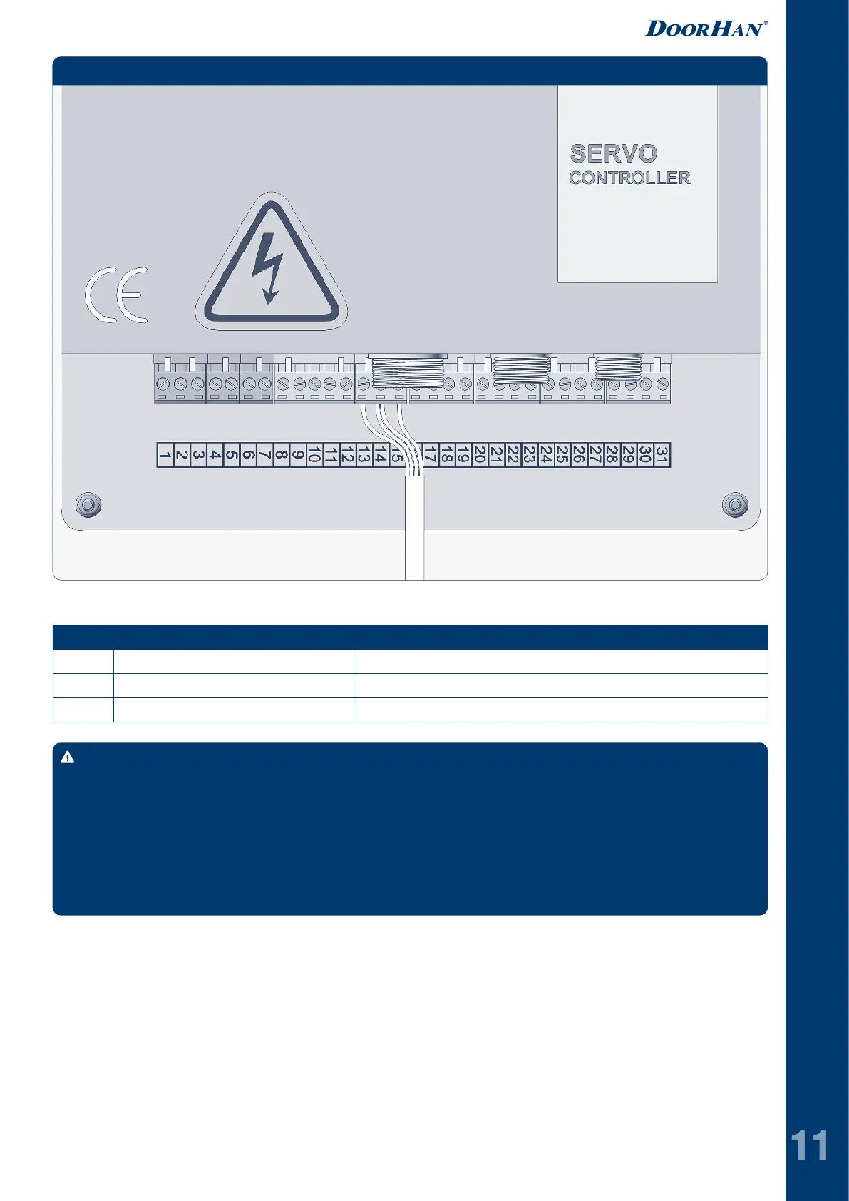
13 DC 24 В + Red
14 Com/Gnd White and black
15 Safety input 1 Yellow
Table 9. Safety edge connection (0,75 kW)
WARNING!
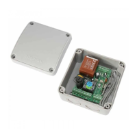
Prior to safety edge connecting take off the cover from the module. Make sure the yellow wire is connected to the
NO contact.
If the device does not work, remove the TS6 transmitter (part no. 180-589) from the door leaf and compare the
last six figures on the transmitter's label with the six figures on the RB61 receiver's label (part no. 180-588). The
figures must be the same.
If for some reason the figures do not match or the edge does not work, it is necessary to pair the receiver with the
transmitter.
Fig. 16. RB61 safety edge connection, part no. 180-589 (0,75 kW)
To pair the transmitter and receiver: turn off the power of the control unit; unscrew the four screws on the
receiver cover; remove the receiver cover; turn on the power of the control unit, the LED on the receiver
board will turn red; press the safety profile 4 times with an interval of 1 second. The LED on the receiver
board will start blinking slowly. Turn off the power to the control unit for 5 seconds, then turn it on again.
Press the safety edge again, the receiver and transmitter are paired. Assemble everything in the reverse order and check the
operation of the safety edge.
 Loading...