2
1800-060 Issued 7-19
Version A
RING
CLCK
SENSE
SPK
VOL
FEEDBACK
MIC VOL
KEYPAD
321
321
321
NO
HS
TONE
OFF
TONE
ON
HF
NC C
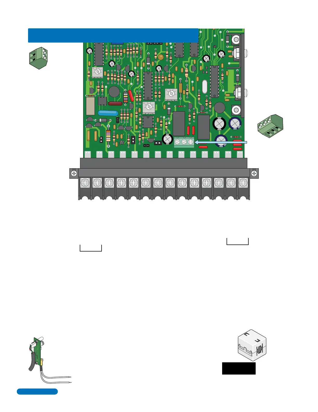
Phone Line Connection
Ring
16AC16AC
BAT NC NO
C
SPKR COMMICGPSWCGNDPHONE
1234567891011121314
Main Terminal
16 VAC Input Power
20 VA Minimum
16 VAC Input Power
Standby Battery POSITIVE (12 VDC, .7 Ah, SLA) (connect negative to terminal 8)
Relay 1 Normally Open – 30 Volt, 3 Amp max.
Relay 1 Normally Closed – 30 Volt, 3 Amp max.
Speaker Output (Purple Wire).
Relay 1 Common
Common for Switch Input 1 terminal #4, speaker, Standby Battery NEGATIVE
Microphone ground Input (White Wire).
MIC
Microphone Input (Green Wire).
Switch Input 1. A closure between terminals 4 and 8 will cause Relay 1 to activate for the
programmed strike time or dial a preprogrammed phone number – see section 3.1.7.
Postal Switch connection.
Earth Ground Only (See Section 2.1.3). NOT a low voltage common.
Phone Line Connection
Tip
Switch Input 2
Terminal
Non-Removable
Relay 2 Terminal
Non-Removable
100 ft. max. with 18 AWG wire.
200 ft. max. with 16 AWG wire.
Install ferrite filter on these wires - see section 2.1.5.
Located in the
upper left corner
of circuit board.
NO
NC
C
Normally Open – 30 Volt, 3 Amp max.
Normally Closed – 30 Volt, 3 Amp max.
Common – 30 Volt, 3 Amp max.
A closure between these
terminals will cause Relay 2
to activate for the
programmed strike time or
dial a preprogrammed
phone number (see section
3.1.7).
2
1
800 ft. max. with 24 AWG wire.
1600 ft. max. with 22 AWG wire.
(Wiring MUST be twisted and isolated from the ground)
Ferrite
Filter
QUICK GUIDE: Terminal Descriptions
See page 21 for terminal wiring.
Do Not Connect Power
To A Receptacle
Controlled By A Switch.
UL 294
Tamper
Switch
Located under
microphone board
(See Section 1.7).
Quick Guide - 1
 Loading...