Do you have a question about the Doosan DL250-3 and is the answer not in the manual?
Provides essential safety instructions for operating and servicing the machine, emphasizing understanding manual content and decals.
Lists the models and serial number ranges to which the safety section applies, including DL300-3 and DL350-3.
Explains the use of safety messages and decals, including signal words like DANGER, WARNING, and CAUTION.
Discusses the location and importance of safety labels (decals) on the machine and the need for their maintenance.
Outlines general safety responsibilities for operators, including understanding the machine and work site rules.
Step-by-step instructions for removing the cylinder head, including handling EGR components and manifold detachment.
Procedures for installing a new cylinder head, including cleaning, lubrication, gasket replacement, and bolt tightening.
Detailed guide on removing and installing engine valves, including spring collets and proper assembly techniques.
Instructions for replacing valve stem seals using specialized tools and proper handling procedures.
Procedure for replacing valve seat inserts, including using pullers, chilling inserts, and machining if necessary.
Steps for removing and installing valve guides using specific drifts and ensuring proper seating.
Guidance on replacing injector sleeves, including surface preparation and installation using specialized tools.
Instructions for replacing valve bridge guide pins, requiring removal of intake and outlet valves.
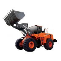
This document is a Shop Manual for the Doosan DL300-3 and DL350-3 Wheel Loaders, covering models with serial numbers 10001 and up, published in April 2012. It provides comprehensive instructions for the maintenance and repair of these heavy-duty machines, ensuring safe and efficient operation.
The manual begins with a critical "Safety" section, emphasizing the importance of understanding and adhering to safety protocols. This section, titled "Wheel Loader Safety," is a foundational component, detailing safety instructions, applicable models, safety messages, general safety guidelines, transportation safety, operation safety, maintenance safety, and considerations for various environmental and circumstantial factors. It highlights the "Safety Alert Symbol" and explains the signal words "DANGER," "WARNING," and "CAUTION," which are used throughout the manual to indicate potential hazards and the necessary precautions. The manual stresses that safe operation is the operator's responsibility, requiring trained and authorized personnel to follow all rules, regulations, and instructions. It warns against operating the machine under the influence of drugs or alcohol and emphasizes the importance of clear communication, such as hand signals, when working with others. Furthermore, it mandates that all guards and shields must be installed and in proper working order, and that safety features like the pilot cutoff switch and seat belt must be understood and used at all times. The manual explicitly states that safety features should never be removed, modified, or disabled. Operators are also advised to be aware of underground and overhead utility lines. A crucial point is "Know Your Machine," which instructs operators to be familiar with all controls, gauges, signals, indicators, and monitor displays, as well as the machine's rated load capacity, speed range, braking and steering characteristics, turning radius, and operating clearances. It also reminds operators that environmental conditions like rain, snow, ice, loose gravel, soft ground, and slopes can impact the machine's operating capabilities.
Following the safety guidelines, the manual delves into "Specifications" for the DL300-3 and DL350-3 models, providing detailed technical data essential for proper maintenance and repair. The "General Maintenance" section offers instructions for routine upkeep and lists standard torques, which are critical for ensuring that fasteners are tightened correctly to prevent component failure.
A significant portion of the manual is dedicated to the "Engine," specifically the DC9 engine. This section covers various aspects of engine maintenance and repair, including detailed procedures for cylinder head removal and installation. For instance, it provides step-by-step instructions for removing the water-cooled EGR cooler, exhaust manifold bolts, cooling system bleeder hose, cable duct, and cable ties for the cable harness. It includes important warnings about the sensitivity of fuel system components to dirt, advising thorough cleaning and plugging of connections with lint-free rags and tape. The manual also emphasizes the need to mark all parts in the fuel injection system and valve mechanism to ensure they are reinstalled in their original positions. Instructions for removing injectors, high-pressure pipes, and connections are also provided. For installation, it details checking liner height, cleaning cylinder head and block, lubricating threads, installing new gaskets, and tightening cylinder head and intake manifold bolts in a specific sequence and to specified torques. A crucial note is that cylinder head bolts can only be reused three times, and a mark should be made with a center punch on the bolt head each time it's reused. If a bolt already has three marks, it must be replaced. The manual also covers the installation of the cable bracket bolt, lower rocker cover, pushrods, valve bridge, and rocker arm housing, with a reminder to lubricate the valve bridge and rocker arm housing with engine oil.
Further engine-related procedures include "Removing and Installing Valves," which requires protective goggles due to the risk of flying metal parts. It outlines how to remove split collets, valve spring collars, springs, and valves using specialized tools. For installation, it warns against mixing parts from different versions of the combination valve and provides instructions for lubricating parts, inserting valves, and installing valve springs and collars. The manual also describes "Replacing a Valve Stem Seal" and "Replacing the Valve Seats," including the use of specific tools and the importance of cooling valve seat inserts to -80°C for rapid pressing. It also addresses "Replacing the Valve Guides" and "Replacing the XPI Injector Sleeves," with a note that the cylinder head must be removed for the latter. The "Replacing the Valve Bridge Guide Pins" section also requires cylinder head removal and specifies the removal of outlet and intake valves.
The "Drivetrain" section covers the transmission and torque converter (ZF 4WG and ZF 5WG options), transmission error codes (ZF), axle (ZF - MT-L 3085 II / 3095 II), and driveshaft, providing essential information for maintaining these critical power transmission components.
The "Brake" system is thoroughly detailed, including the service brake, supply valve, charging block, parking brake, brake pedal valve, and accumulator, ensuring that all aspects of the braking system can be properly serviced.
"Steering" components are also covered, with sections on the power steering system, steering unit, steering pump, flow amplifier, jerk softener and accumulator, and emergency steering, all vital for the machine's maneuverability and control.
The "Tank" section provides information on the oil tank and fuel tank, crucial for fluid management.
"Hydraulics" is a comprehensive section, detailing the main pump, main control valve, 3rd control valve (option), load isolation system, cooling system, and pilot system. It also includes a "Hydraulic Schematic DL300-3 / DL350-3," which is indispensable for diagnosing and repairing hydraulic issues.
Finally, the "Electrical System" section covers the air conditioner, general electrical system information, and an "Electrical Schematic DL300-3 / DL350-3 / DL420-3 / DL450-3," providing the necessary diagrams and instructions for electrical troubleshooting and repair across multiple models.
Overall, this shop manual is an exhaustive resource designed to guide technicians through the complex processes of maintaining, diagnosing, and repairing the Doosan DL300-3 and DL350-3 Wheel Loaders, with a strong emphasis on safety and adherence to precise procedures.
| Brand | Doosan |
|---|---|
| Model | DL250-3 |
| Category | Compact Loader |
| Language | English |