INSTALLATION INSTRUCTIONS
1900-INST-EN-2017/03
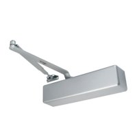
PARALLEL ARM - PUSH SIDE MOUNTING
DOOR CLOSER ADJUSTMENT
TOP JAMB - PUSH SIDE MOUNTING
DOOR CLOSER FEATURES
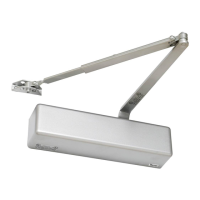
REGULAR ARM - PULL SIDE MOUNTING
INSTALLATION REQUIREMENTS
60-90 (27-41)
85-140 (38-63)
125-190 (57-86)
175-265 (80-120)
250-330 (113-150)
Door weight
lbs (kg)
-
36" (914mm)
42" (1067mm)
Exterior
54" (1372mm)
Maximum door size
36" (914mm)
42" (1067mm)
48" (1219mm)
54" (1372mm)
Interior
60" (1524mm)
CW turns
of adjusting
screw
0
3
6
9
12
Power
2
3
4
5
6
• Surface mounted
• Adjustable power range from 2 to 6 (factory preset to 3).
• Adjustable speed control
• Adjustable backcheck
• Barrier free model (with delayed action) has adjustable power
range from 1 to 4 (factory preset to 2). Door closers set for
barrier free applications may not have sufficient force to latch
the door under certain exterior force loading conditions.
CLOSING SPEED CYCLE
The door closer closing speed is controlled by two different speed control valves: SWEEP speed control
valve and LATCH speed control valve.
• To adjust SWEEP speed turn the closing sweep speed control valve counter-clockwise (CCW) for
faster speed and clockwise (CW) for a slower speed.
• To adjust the LATCH speed turn the latching speed control valve counter-clockwise (CCW) for
faster speed and clockwise (CW) for a slower speed.
BACKCHECK CONTROL
The backcheck is used to cushion the door opening, after about 75° opening.
• To adjust BACKCHECK cushion turn the backcheck control valve counter-clockwise (CCW) for a
softer cushion and clockwise (CW) for a harder cushion.
DEL AYED AC TION
Delayed Action (DA) is available with Barrier Free (BF) model. An additional speed control valve delays
the door closing for few seconds. Then the door starts closing slowly up to about 75°. Once past the
75°, the door closes at the normal closing speed.
• To adjust the DELAYED ACTION turn the DA speed control valve counter-clockwise (CCW) for a
shorter delay and clockwise (CW) for a longer delay.
CAUTION
Do not turn any of the adjusting valves more than four (4) turns CCW from the fully closed
position, as the valves (screws) may become dislodged from the door closer body, resulting in
loss of internal fluid and failure of the device.
SPRING POWER CONTROL
Door closer is provided with an adjustable spring force to compensate for different door sizes and weights. Factory preset to size 3 (1900BF factory preset to size 2).
• To increase spring force turn power spring screw clockwise and to decrease spring force turn the power spring screw counter-clockwise.
• To determine the approximate door closer size required for door size, refer to Table 2.
• Door must be hung on ball bearing or antifriction hinges.
• Door and frame must be properly reinforced at the door closer mounting areas.
• For non-labelled wood doors pre-drill and use wood screws.
• For steel reinforced hollow metal doors, drill and tap for the appropriate machine screws.
• For non-reinforced hollow metal doors and labeled wood doors, drill and use sex-nut bolts.
• For steel frames drill and tap for the appropriate machine screws.
• For optional drop plates, hold open function, cushion rigid arm installation see separate
installation instructions.
• Door closer should not be installed on an exterior side of a door or door frame surface.
Spring power
adjusting screw
Backcheck
Delayed
Action
(optional)
Sweep
speed
Latch
speed
ILLUSTRATION 1
Backcheck
range
CLOSING
CYCLE
OPENING
CYCLE
Sweep
speed
Delayed
action
Latch
speed
ILLUSTRATION 2
ILLUSTRATION 7
ILLUSTRATION 9
ILLUSTRATION 6
Door Opening
Dimension A
120°
180°
7 3/32" (180mm)
4 1/2"
(114mm)
MAX.
3 15/16" (100mm)
ILLUSTRATION 10
Door opening
Dimension A
120° 9 1/8" (241mm)
5 7/8" (149mm)
Dimension B
6 1/8" (156mm)
2 9/16" (65mm)
TABLE 4
180°
TABLE 3
TABLE 1
Door
Opening
Dimension A
120°
180°
7 3/32" (180mm)
3 15/16" (100mm)
TABLE 2
Maximum door size
CW turns
of adjusting
screw
Power
1
2
3
4
0
4
8
12
5 lbs opening force
36" (914mm)
48" (1219mm)
–
36" (914mm)
42" (1067mm)
Interior Exterior
ILLUSTRATION 5
FOREARM LINK
POWER
ADJ.
PRELOAD
MAIN
ARM
MAIN
ARM
LEFT HAND DOORRIGHT HAND DOOR
OUTSIDE OUTSIDE
PRELOAD
L
R
S
L
R
S
33-65 (15-30)
60-90 (27-41)
85-140 (38-63)
125-190 (57-86)
Door weight
lbs (kg)
BARRIER FREE MODEL - POWER 1-4
REGULAR MODEL - POWER 2-6
Hinge Centreline
Top Jamb
Door
ILLUSTRATION 8
LEFT HAND REVERSEDRIGHT HAND REVERSED
PRELOADPRELOAD
FOREARM
MAIN
ARM
MAIN
ARM
Hinge Centreline
Underside of
Door Stop
(soffit)
Underside of
top jamb
(soffit)
5 3/8"
136mm
1 3/4"
44.5mm
1 1/4"
32mm
7/8"
22mm
11 1/ 8"
282mm
DOOR CLOSER
DOOR CLOSER
9/16"
14.3mm
A
1 1/8"
(28.5mm)
11 1/ 8"
(282mm)
B
A
3"
(76mm)
2 3/4"
(70mm)
7/16"
(11mm)
3/8"
(9.5mm)
2"
(51mm)
ILLUSTRATION 3
Hinge
Centreline
Top Jamb
Arm shoe
Door
5 3/8"
136mm
1 3/4"
44.5mm
1 1/4"
32mm
7/8"
22mm
11 1/ 8"
282mm
DOOR CLOSER
1 1/8"
28.5mm
A
Spring Power Adjustment
POWER
ADJ.
Parallel Arm Bracket
OUTSIDE OUTSIDE
VIEW FROM INSIDE
ILLUSTRATION 4
Regular Arm Installation
Closer installs on
Pull/Hinge side of door
Illustrated:
Right hand door (RH)
VIEW FROM INSIDE
VIEW FROM INSIDE
ILLUSTRATION 11
L
R
S
L
R
S
RIGHT HAND REVERSED
45°
LEFT HAND REVERSED
PARALLEL
BRACKET
45°
PRELOAD
MAIN ARM
FOREARM
POWER
ADJ.
POWER
ADJ.
OUTSIDE OUTSIDE
Arm shoe
NOTE: Parallel arm installation reduces the closing force by 25%
48" (1219mm)
42" (1067mm)
INSTALLATION INSTRUCTIONS
1. Adjust spring power to match door size (see Table 2) and select the desired door opening angle as per Table 1.
2. Prepare mounting holes and mount closer on door to dimensions shown. (Spring power adjustment screw must
be facing AWAY from the hinges).
a) For wood or sheet metal screws installation pre-drill 3/16" (4.5 mm) diameter holes
b) For machine screws installation drill and tap for 1/4 -20 UNC thread.
c) For fire rated doors use machine screws or through-bolts. (Through-bolts not supplied)
3. Prepare mounting holes and mount forearm & arm shoe on the frame's top jamb to shown dimensions.
a) For wood or sheet metal screws installation pre-drill 3/16" (4.5 mm) diameter holes.
b) For machine screws installation drill and tap for 1/4 -20 UNC thread.
4. Install main arm on top pinion shaft approximately perpendicular the door (see illustration 5). Secure main arm
using provided screw and lockwasher assembly.
5. Insert forearm link into the forearm and adjust the length so that the forearm is perpendicular to the door
frame while connected to the preloaded main arm. Firmly secure the forearm link to the forearm using the
supplied screw and serrated washer.
6. Adjust door closing and latching speeds, backcheck and delayed action (if applicable) as per door speed
control instructions above.
7. Prepare cover by inserting the pinion hole cover at the appropriate location for the door closer's orientation
and attach to door closer with supplied screw.
INSTALLATION INSTRUCTIONS
1. Adjust spring power to match door (see Table 2) and select the desired door opening angle in Table 4
2. Prepare mounting holes and mount closer on door to dimensions shown, with spring power adjustment
screw TOWARD the hinges.
a) For wood screw installation pre-drill 3/16" (4.5 mm) diameter holes.
b) For machine screw installation drill and tap for 1/4 -20 UNC thread.
c) For fire rated doors use machine screws or through-bolts.
3. Prepare mounting holes and mount parallel arm bracket onto the frame door stop face (soffit).
a) For wood screw installation pre-drill 3/16" (4.5 mm) diameter holes.
b) For machine screw installation drill and tap for 1/4 -20 UNC thread.
c) Machine screw installation is recommended.
4. Attach main arm to door closer top shaft as follows (refer to illustration 11). Place wrench on bottom shaft and turn toward hinge jamb about 45°.
Place main arm on top shaft, insert main arm screw into top of shaft and tighten.
5. Remove the arm shoe from forearm link then attach the forearm link to the parallel arm bracket as shown.
6. Open door and insert forearm link into the forearm and close door. Adjust the length until the main arm is parallel to the door surface.
Firmly secure the forearm link to the forearm using the supplied screw and serrated washer.
7. Adjust door closing and latching speeds, backcheck and delayed action (if applicable) as per door speed control instructions above.
8. Prepare cover by inserting the pinion hole cover at the appropriate location for the door closer's orientation and attach to door closer with supplied screw.
Use these mounting hole
positions if frame top jamb height
is less than 2-3/8" (60 mm)
Forearm Link Forearm
CAUTION: An incorrectly installed or improperly adjusted door closer can cause
property damage or personal injury. These instructions should be followed to avoid the
possibility of misapplication or maladjustment.
75° 75°
INSTALLATION INSTRUCTIONS
1. Adjust spring power to match door size (see Table 2) and select the desired door opening angle in Table 3
2. Prepare mounting holes and mount closer on frame to dimensions shown.
(Spring power adjusting screw must be facing AWAY from the hinges).
a) For wood or sheet metal screw installation pre-drill 3/16" (4.5 mm) diameter holes.
b) For machine screw installation drill and tap for 1/4 -20 UNC thread.
3. Prepare mounting holes and mount forearm link & arm shoe on the door to shown dimensions.
a) For wood or sheet metal screw installation pre-drill 3/16" (4.5 mm) diameter holes.
b) For machine screw installation drill and tap for 1/4 -20 UNC thread.
c) For fire rated doors use machine screws or through-bolts.
4. Install main arm on bottom pinion shaft approximately perpendicular the door
(see illustration 8). Secure main arm using provided screw and lockwasher assembly.
5. Insert forearm link into the forearm and adjust the length so that the forearm is perpendicular to
the door frame while connected to the preloaded main arm. Firmly secure the forearm link to the
forearm using the supplied screw and serrated washer.
6. Adjust door closing and latching speeds, backcheck and delayed action (if applicable) as per
door speed control instructions above.
7. Prepare cover by inserting the pinion hole cover at the appropriate location for the door closer's
orientation and attach to door closer with supplied screw.
Top Jamb Installation:
Closer installs on frame on Push/Stop side of door
Illustrated: Right hand reversed (RHR)
Parallel Arm Installation:
Closer installs on frame on Push/Stop side of door
Illustrated: Right hand reversed (RHR)
Spring Power Adjustment
Spring Power Adjustment
Main Arm
FOREARM LINK
FOREARM
LINK
FOREARM
Document provided as-is, manufacturer reserves the
right to make technical changes without prior notice.