Do you have a question about the Dorex 1901 and is the answer not in the manual?
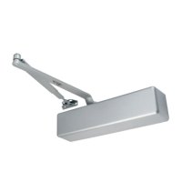
Step-by-step guide for mounting the door closer and parallel arm components on the door.
Guidance on adjusting closing speed, latch speed, hold-open, and backcheck.
Instructions for fitting the external cover and the shaft cover onto the door closer.
Table and details for selecting and adjusting spring power based on door size.
Visual information to correctly identify left-hand and right-hand door configurations.
Specific installation steps for the regular arm closer on the pull side of the door.
Adjusting speeds and hold-open for the regular arm installation.
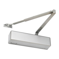
Specific installation steps for the top jamb closer on the push side of the door.
Adjusting speeds and hold-open for the top jamb installation.
The Dorex 1901 is a door closer with a friction hold-open arm (1901-ARMF) designed for various mounting configurations: Regular Mount (Pull Side), Top Jamb Mount (Push Side), and Parallel Mount (Push Side). This device is intended to control the closing and latching of doors, offering adjustable spring power, closing speeds, and a hold-open function.
The primary function of the Dorex 1901 is to provide controlled door closing, preventing slamming and ensuring the door latches properly. It incorporates a hydraulic mechanism that regulates the door's speed throughout its closing arc. A key feature is the friction hold-open arm, which allows the door to be held open at a desired angle, providing convenience for passage or ventilation. The device is handed, meaning specific installation instructions apply for right-hand and left-hand doors, with opposite installations required for the alternative hand.
The spring power is adjustable to accommodate different door sizes and weights. The adjustment is made by turning a screw, with specific turns required for each power setting:
The door closer features adjustable valves for controlling the closing sequence:
| Brand | Dorex |
|---|---|
| Model | 1901 |
| Category | Door Opening System |
| Language | English |