EACH SET CONTAINS THE FOLLOWING PARTS
BAG: PARTS INCLUDED:
1. Strike with wood & machine screws
2. Head & end cover chassis with wood & machine screws
3. Latch & strike filler plate with wood & machine screws
END SUPPORT
BRACKET
END COVER
CHASSIS
STRIKE FILLER
PLATE
ON FRAME
LATCH FILLER
PLATE
ON DOOR
COVER
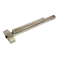
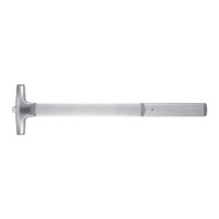
INSTALLATION INSTRUCTIONS
PANIC RIM MODEL
WOOD
OR MACHINE
SCREWS
PUSH BAR
DOGGING:
Depress push bar, insert dogging key
and turn 90°. The push bar will
remain depressed and the latch will
remain retracted.
STRIKE
8500P-INS 2018-06
Page 1
GENERAL NOTES
Before installing exit device, verify or note the following:
1. The door surface must be flat and properly
reinforced at the exit device mounting locations. If
door is not reinforced, the door surface may
collapse or bow-in, causing malfunction in the exit
device operation.
2. Door must be properly fitted and hung.
3. The 3' exit device model can be cut to fit doors from
30 to 38" (762 to 965 mm) in width.
The 4' exit device model can be cut to fit doors from
38 to 48" (965 to 1219 mm) in width.
4. Determine door handing (see illustration above). Rim exit
device is non-handed.
5. For wood doors or hollow metal doors use wood/sheet
metal screws, and for metal reinforced doors drill & tap
and use machine screws. (Refer to Template document).
RIGHT HAND REVERSED LEFT HAND REVERSED
OUTSIDE
OUTSIDE
DOOR HANDING
INSIDE
INSIDE
CAUTION:
Exit device components must be
installed flush to a flat surface