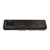
Figure 1.6: LED Drivers; 1-, 2- and 4-channel
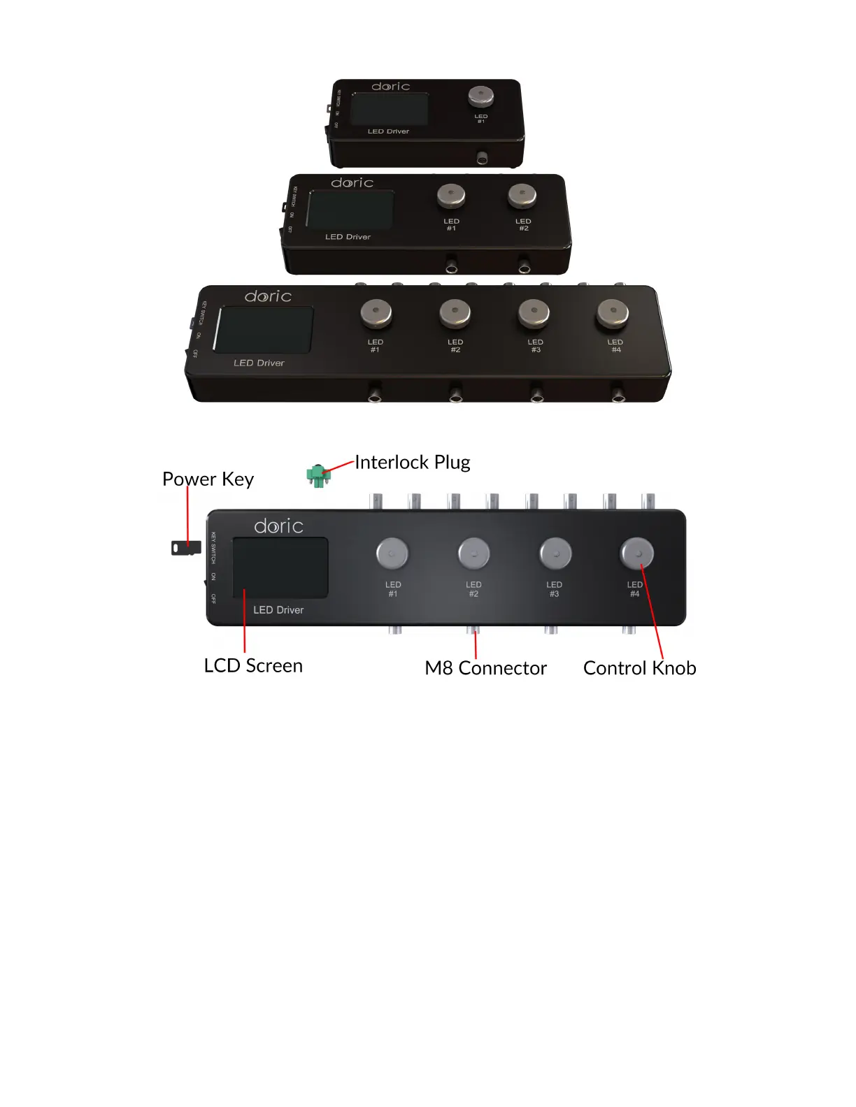
Figure 1.7: Front view of a 4-channel LED Driver
• The Power key must be properly inserted into the key switch to enable operation of the light source(s) connected
to the driver. Note that, despite its similar shape, the power key is not a standard micro SD card such as those used
in some digital cameras. Do not attach the Key to a key fob or similar holder; this may prevent proper insertion of
the Power key.
• The M8 connector is used to link the driver and LED.
• The Interlock Connector Plug (Fig. 1.8) allows the user to connect the driver to an interlock system. It is recom-
mended to connect the interlock plug to a laboratory interlock system. This is critical when using LEDs in the UV
or Infrared spectrum, as they are invisible to the naked eye.
• The Input BNC allows the control of the LED driving current of the corresponding source with an analog or TTL
signal.
• The Output BNC are used to monitor the driving current of the corresponding light source.
• The 12 VDC power input connects the driver to its 12 VDC power supply.
• The USB-B Connector allows the driver to be connected to a computer using a USB-A/USB-B cable.
Chapter 1. Fiber Photometry Systems at a Glance 8
 Loading...