EasyManua.ls Logo

Dorma STE 400 User Manual

Dorma STE 400
4 pages
To Next Page IconTo Next Page
Page #1 background imageLoading...
Page #1 background image
DORMA
STE 400
STE 400-RR
WN 058097-45532
12/10
1
2.
1.
3.
4.
178 178
25
25
123123
212,8212,8
28
28
1 mm
Schlossfalle
Door Latch
Türöffnerfalle
Strike keeper
Türöffnerfalle
Strike keeper
1
optionale
Erweiterungslippe
optional
extension lip
Falle
Strike Keeper
2a
Montage / Mounting
2b
STE 400STE 400
STE 400-RRSTE 400-RR
Bei verschlossener Tür darf die
Schlossfalle keinen Druck auf die
Falle des Türöffners ausüben.
When door is closed, make sure
there is no back pressure on the
strike keeper.
Question and Answer IconNeed help?

Do you have a question about the Dorma STE 400 and is the answer not in the manual?

Dorma STE 400 Specifications

General IconGeneral
BrandDorma
ModelSTE 400
CategoryDoor locks
LanguageEnglish

Summary

Mounting and Installation

Optional Extension Lip

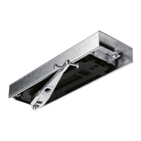
Details on the optional extension lip for the mounting process.

Strike Keeper and Door Latch

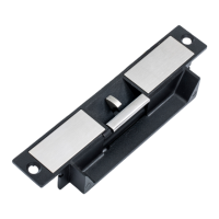
Information regarding the strike keeper and door latch components.

Mounting Instructions and Safety Notes

Key operational instructions and critical safety warnings for mounting.

Wiring Diagram and Connections

Power and Control Wiring

Instructions for connecting power supply and control signals like PTO/PTL.

Monitoring Sensor Connections

Details on connecting LSS, DSS, and ATS sensors for monitoring functions.

Technical Specifications and Safety

Power supply data, input requirements, and static sensitive device warnings.

Switching Power Modes (PTL/PTO)

PTL/PTO Mode Conversion Guide

Step-by-step procedure for switching between Power-to-Lock and Power-to-Open modes.

Related product manuals