© 2023 No reproduction in whole or in part without prior written approval. 55101_Instructions
55101: CHOKE CONVERSION KIT PAGE 2 OF 9
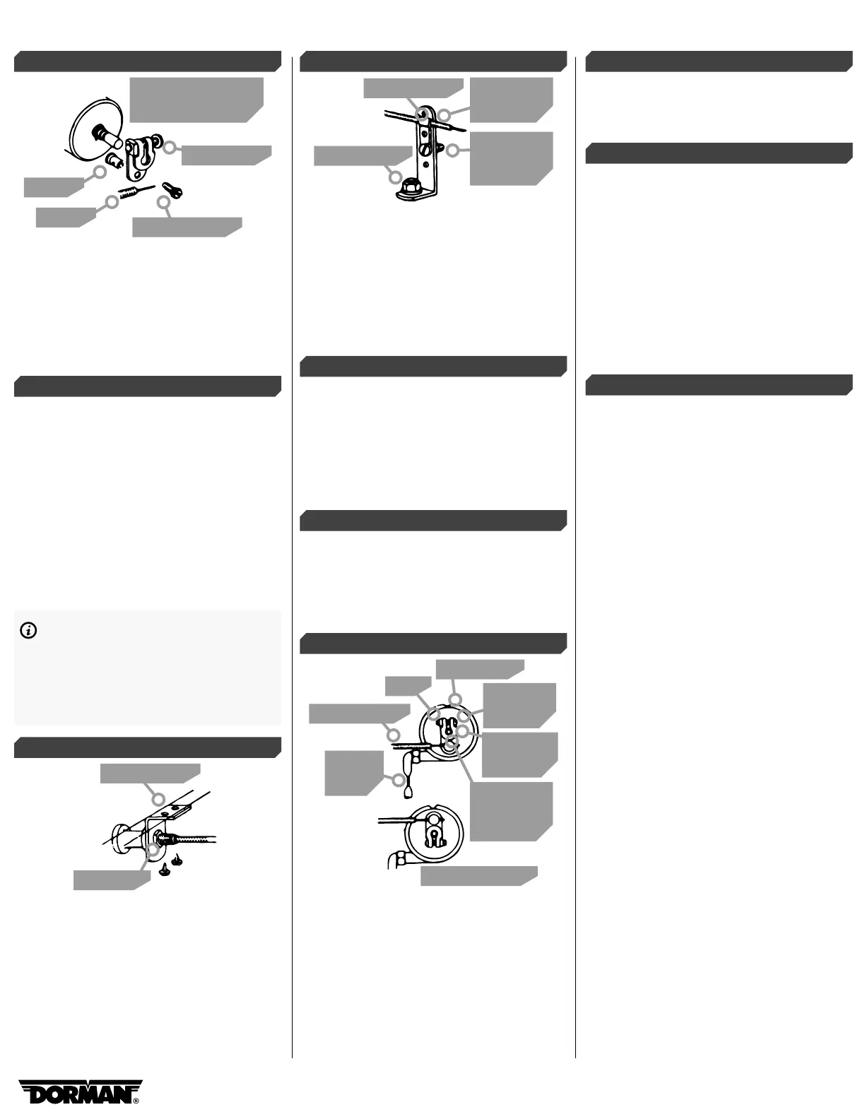
STEP 4:
Collar
Cable
Long screw
Machine screw
Mount on activator
shaft outside cap
Mount the swivel assembly on the shaft on the
outside of the cap. This requires two operations.
First, assemble long screw and nut as shown, but
do not tighten. Second, insert the small machine
screw at the bottom of the assembly and screw
into the collar. Do not tighten because the choke
control wire will have to be inserted in the collar.
STEP 5:
Place the cap as assembled on the carburetor,
making sure the U-shaped opening in the
activator lever catches the choke tang. Using the
same screws and clip which held the automatic
choke in place, fasten the new choke cap and
conversion mechanism on the carburetor. Move
the buttery on top of the carburetor back and
forth, making certain the activator shaft and
swivel assembly are also moving. If they are not,
the choke tang is not engaged in the U-shaped
opening on the activator lever or the shaft is not
set deep enough to catch the tang. Adjust as
necessary and proceed.
NOTE: Some carburetors have a double
choke tang. If the tangs are metal, use
pliers to bend one of the prongs down 90°.
If they are nylon, use cutters to remove
one of the prongs. Next, install so that the
lever catches the remaining tang.
STEP 6:
Dash bracket
Lock nut
Locate a convenient position on the underside
of the instrument panel (dash) for mounting the
dash bracket. Use the bracket as a template to
drill two 1/16” diameter holes and the mount
bracket with two supplied sheet metal screws.
STEP 7:
Manifold nut
Cable clamp
Manifold
L-bracket
Cable
clamp nut
and bolt
Remove the lock nut from the control cable
and thread the cable through the dash bracket.
Replace the nut over the control cable and fasten
the control cable securely to the bracket. Thread
control cable through the rewall. For best results,
use a wire hole near the top and center
of the rewall. You may have to drill a hole
on some models.
STEP 8:
Mount the manifold L-bracket to the manifold
in line with the swivel assembly. Use a manifold
bolt that is within 6 inches from the carburetor.
The manifold L-bracket may then be bent, if
necessary, to create better alignment. On some
four and in-line six cylinder engines, the L-bracket
can be mounted on the rewall or other location.
STEP 9:
Place the choke cable clamp over the choke
cable. Using the remaining screw and nut,
assemble to the manifold L-bracket. Use the
bracket hole giving the best alignment with the
swivel assembly.
STEP 10:
Control cable
Nut
Machine
screw
Swivel
assembly
Plastic cap
Shaft
and lever
assembly
Alternate set-up
Crimp
tight
Determine the direction in which your choke
buttery operates, so that when installation is
completed, the choke buttery will close when
you pull out the control on the instrument
panel and open when you push it in. This is
done by having the swivel assembly point down
to the manifold or straight up. Once you have
determined the correct position, tighten the
screw nut assembly on the shaft.
STEP 11:
Insert the choke cable wire inside the cable and
through the hole in the collar tting referred to in
Step 4.
STEP 12:
To adjust the manual choke, have an assistant
sit in the automobile to depress and hold the
accelerator all the way down and operate the
choke by pulling it in and out. When the knob is
pulled all the way in against the dash bracket,
the choke buttery should be completely open.
If adjustment is needed, loosen the screw on the
choke wire, open the choke buttery to its upright
position and then retighten. Adjustments may
also be made by loosening and re-adjusting the
swivel assembly on the shaft. Tighten all ttings
and reinstall air lter.
STEP 13:
In the event the air lter housing interferes with
the swivel assembly, be sure the assembly is all
the way on the shaft, against the cap. If the swivel
assembly is in the up position and responsible
for the interference, disconnect the control cable
from the swivel assembly and the large L-bracket.
Re-route the cable around the carburetor. Re-
locate the large L-bracket on the opposite side of
the engine and mount it in a convenient location.
Loosen the swivel assembly and set it down as
shown in the top part of Step 10. Reconnect the
control cable to the bracket and swivel assembly
as fed from the other side of the carburetor.
This will allow the choke buttery to operate
normally with the swivel downward and should
solve clearance problems. The activator shaft
which extends beyond the swivel assembly may
also interfere with the air lter housing. This
extra length of shaft may be cut with a hacksaw.
Now you have a new, properly working manual
choke. If you have a heat tube connected to the
carburetor body, crimp tight with a pair of pliers,
as shown in Step 3.
 Loading...