EasyManua.ls Logo

Dorman 55101 - User Manual

Dorman 55101
9 pages
Print Icon
To Next Page IconTo Next Page
Loading...
Dorman Products, Inc. Corporate Oce and Customer Service: 1-800-523-2492.
Disclaimer: It is impossible in these instructions to account for all possible circumstances or situations that you may experience when
attempting to install this product. Please consult with a qualied auto technician before attempting to perform any work you are not qualied to
do. Automobiles can be hazardous to work on; be sure to take all necessary safety precautions. Failure to do so may result in property damage
or personal injury. Certain motor vehicle standards and performance requirements may apply to your motor vehicle (such as Federal Motor
Vehicle Safety Standards by the National Highway Trac Safety Administration). Be sure that your work is performed in accordance with such
standards and that you do not disable any motor vehicle safety feature.
INSTRUCTIONS
PAGE 1 OF 9
CHOKE
CONVERSION KIT
55101
BEFORE YOU BEGIN:
Always wear proper safety
equipment when performing repairs.
Ensure at your point of purchase
that this part ts your exact
vehicle conguration.
Reference the appropriate service
manual for your vehicle. If you do
not have a service manual, and do
not have the training or experience
to perform the necessary
procedures correctly, seek the
services of a qualied technician.
NEED HELP?
Please call our Technical Support
team for assistance from our team of
certied automotive experts.
1-866-933-2911
© 2023 No reproduction in whole or in part without prior written approval.
55101_Instructions
Remove air lter from carburetor and determine the
type of automatic choke on the car. There are two
basic types:
Integrated
choke
If automatic choke thermostat is an integral part
of carburetor body and uses a black cap or plastic
or metal disc, it is an integrated choke. Follow the
rst set of instructions for integrated choke.
Non-integrated
choke
If a rod connects the carburetor choke shaft to
the thermostat mechanism which is located in
the intake manifold, it is a non-integrated choke.
Follow the second set of instructions
for non-integrated choke.
INTEGRATED CHOKE
INSTALLATION
INSTRUCTIONS
STEP 1:
Remove the black plastic cap or metal disc. If a
heat tube is attached to the choke cap, remove
and discard it. Do not remove if it is attached to
the carburetor body. Save all screws, retainers,
clamps, etc., for use in installing this kit. Make
sure the choke shaft and choke buttery operate
smoothly. If not, clean with choke cleaner.
STEP 2:
Determine which of the two plastic caps included
in this kit best ts your carburetor. Discard the
one you will not need. On some carburetors, the
anges of the cap t between the three set pins.
On others, the anges will t securely within the
carburetor body.
STEP 3:
Activator shaft
Breakaway line
Activator lever
Activator shaft
Activator
lever
R-clips
Choke buttery
Crimp tight
with pliers (do
not remove)
Choke
tang
Insert the actuator shaft in the new plastic cap,
with the activator lever inside the cap. If you are
using the larger cap, insert the activator shaft
assembly (rst illustration) in the cap as shown
in the second illustration and set depth. If you
are using the smaller cap, the activator lever will
have to be shortened at the break-away points
as shown in the rst illustration. This is done by
grasping activator lever with pliers above break-
away line and then bending back and forth until
the excess portion breaks away. Do one side at a
time. Set the depth of the activator lever within
the cap so it will catch the choke tang in the
carburetor (third illustration), but not so deep
that the activator will bind on the choke housing.
Once the exact position has been determined,
remove the shaft and install the inside R-clip.
Then place the shaft in position again and install
outer R-clip (second illustration).
Question and Answer IconNeed help?

Do you have a question about the Dorman 55101 and is the answer not in the manual?

Summary

Before You Begin

Integrated Choke Installation

Step 1: Prepare Integrated Choke

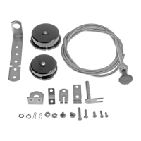
Remove existing choke cap, heat tube, and save components. Ensure choke shaft moves freely.

Step 2: Fit Plastic Caps

Select the correct plastic cap and fit it to the carburetor, ensuring proper flange engagement.

Step 3: Install Activator Shaft

Insert shaft and lever, adjust depth, secure with R-clips, and ensure smooth operation.

Step 4: Mount Activator Shaft Assembly

Assemble and attach the swivel assembly to the activator shaft outside the cap.

Step 5: Mount Choke Cap

Mount the assembled cap, ensuring the activator lever engages the choke tang. Verify smooth movement.

Step 6: Mount Dash Bracket

Locate and mount the dash bracket on the instrument panel for the control cable.

Step 7: Attach Cable Clamp

Remove lock nut, thread cable through dash bracket, secure cable to bracket, and thread through firewall.

Step 8: Mount Manifold L-Bracket

Mount the L-bracket to the manifold or firewall for alignment with the swivel assembly.

Step 9: Secure Cable Clamp

Clamp the choke cable to the manifold L-bracket, ensuring best alignment with the swivel assembly.

Step 10: Assemble Swivel and Shaft

Assemble the swivel assembly and shaft with the plastic cap, control cable, and nut.

Step 11: Insert Choke Cable Wire

Insert the choke cable wire through the cable and into the collar fitting.

Step 12: Adjust Manual Choke

Adjust choke butterfly position by loosening wire screw and ensuring full open/closed operation.

Step 13: Resolve Clearance Issues

Reroute cable or cut shaft if air filter housing interferes. Crimp heat tube if applicable.

Non-Integrated Choke Installation

Step 1: Prepare Non-Integrated Choke

Disconnect rod, install dash bracket and control cable as per integrated instructions.

Step 2: Drill Choke Shaft

Center punch and drill a 1/2" deep hole in the end of the choke shaft.

Step 3: Attach Activator S-bracket

Assemble and screw the activator S-bracket into the drilled hole on the choke shaft.

Step 4: Install L-Bracket and Clamp

Install L-bracket and clamp as per integrated instructions, aligning with the activator S-bracket.

Step 5: Set Activator S-bracket Direction

Point S-bracket up or down to ensure butterfly closes when pulling control, opens when pushing.

Step 6: Connect Control Wire

Attach the control wire inside the cable to the S-bracket using the screw and collar.

Step 7: Adjust and Tighten

Adjust the choke as per integrated instructions, then tighten all fittings firmly.

Step 8: Resolve Clearance Issues

Reposition S-bracket or reroute cable if air cleaner causes clearance problems.

Operating Instructions

Step 1: Prime Carburetor

Depress accelerator fully, pull choke cable out to set fast idle.

Step 2: Start Engine

Start the vehicle's engine.

Step 3: Initial Choke Push

Immediately push the choke control in at least 1/4 of the way after engine starts.

Step 4: Final Choke Push

Once the engine has warmed up, push the control cable in all the way.

Dorman 55101 Specifications

General IconGeneral
Part Number55101
ManufacturerDorman
MaterialSteel
ColorBlack
Fit TypeVehicle Specific
Bolt Pattern5 x 114.3 mm
Wheel Stud Quantity5
Wheel Stud Thread SizeM12 x 1.5
PositionFront or Rear

Related product manuals