Fixed and Adjustable Height Stands Set-up, Operation & Maintenance Manual
Dorner Mfg. Corp. 5 851-558 Rev. B
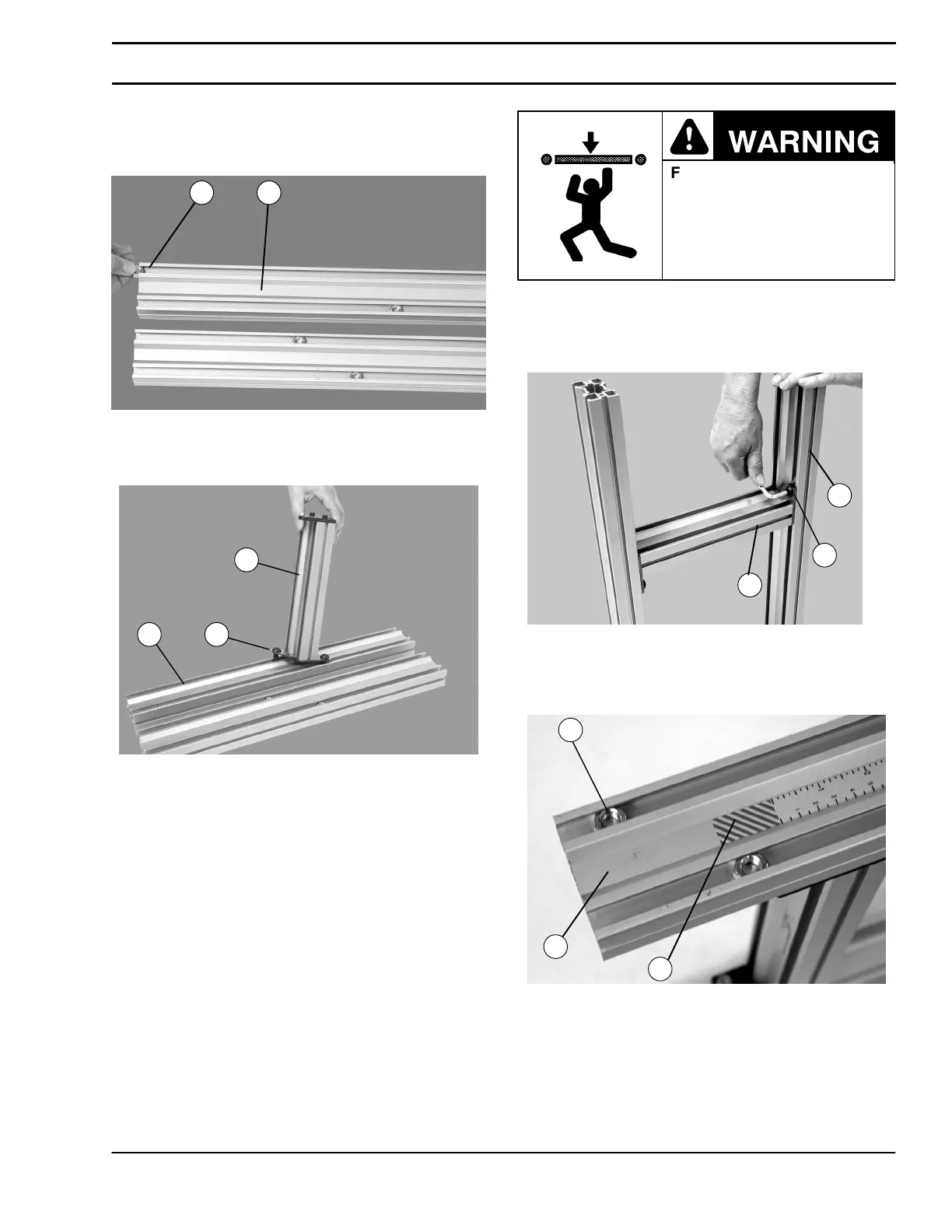
3. On the side opposite height sticker (P of Figure 3)
install one (1) hex nut (Q of Figure 4) into each inside
stand leg (K) t–slot.
Figure 4
Q
K
4. Attach crossmember (M of Figure 5) to stand leg (K)
with button screws (R). Do not tighten.
Figure 5
RK
M
5. Repeat step 4 for opposite stand leg. Make sure to
locate the red warning area (P of Figure 3) on the
same ends of stand legs (K of Figure 5).
Failure to secure screws (R
of Figure 6) may cause
conveyor sections to drop
down causing severe injury.
TIGHTEN SCREWS (R)
AFTER ADJUSTMENT.
6. Upright stand and locate and space crossmember(s)
(M of Figure 6) evenly along stand leg (K). Tighten
crossmember button screws (R) to 150 in–lb (17
N–m).
Figure 6
R
M
K
7. On the end with red warning area (O of Figure 7)
install one (1) hex nut (Q) into each outside stand leg
(K) t–slot.
Figure 7
Q
K
O
Installation


 To Next Page