Fixed and Adjustable Height Stands Set-up, Operation & Maintenance Manual
851-558 Rev. B 4 Dorner Mfg. Corp.
Supports marked with this
symbol must be anchored to
the floor. Supports not
anchored to floor will tip,
causing severe injury or
death.
SUPPORTS MUST BE
ANCHORED TO FLOOR.
DANGER
Exposed moving parts can
cause severe injury.
LOCK OUT POWER before
removing guards or
performing maintenance.
Recommended Installation Sequence (see
Table of Contents for page numbers)
D Assemble stand(s), if required
D Attach stand(s) to conveyor (see Conveyor Installa-
tion, Maintenance & Parts Manual)
D Attach optional diagonal bracing (see Diagonal
Brace Kit Manual)
D Adjust stand height and level (see Adjustment sec-
tion, page 10)
Assembly
Stands Shipped Partially Assembled
Required Tools
D 6 mm Hex Key Wrench
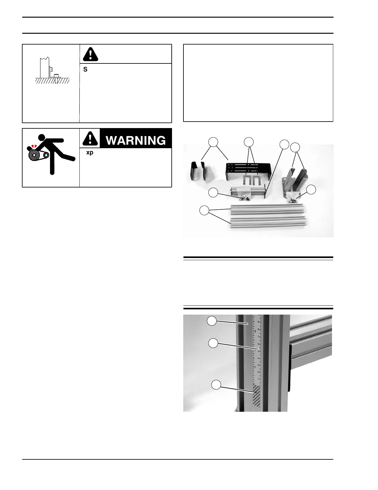
1. Typical components (Figure 2).
Typical Components
H Boots/Foot Plate Assembly (2x)
I Hardware Pack, Standard Stand
J Conveyor Mounting Bracket(s)
(2 possible configurations)
K Vertical Stand Legs (2x)
L Hardware Pack, Crossmember
(quantity as required)
M Crossmembers (quantity as required)
N U–nuts (2x)
Figure 2
K
H
M
N
J
L
I
or
2. Open standard stand hardware pack (I of Figure 2).
NOTE: Stand legs (K of Figure 3) are equipped with a
height sticker (P). Assemble stand legs with the sticker
on the outside and the red warning area (O) at the bot-
tom of the legs.
Shown assembled. See steps 7 and 8 for boot as-
sembly.
Figure 3
K
P
O
Installation


 To Next Page