Fixed and Adjustable Height Stands Set-up, Operation & Maintenance Manual
Dorner Mfg. Corp. 7 851-558 Rev. B
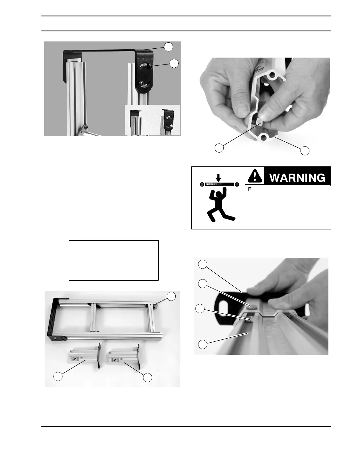
Figure 10
J
S
11. For leveling and height adjustment see page 9.
Stands Shipped Fully Assembled
Required Tools
D 6 mm Hex Key Wrench
1. Typical components (Figure 11).
Typical Components
T Stand Assembly
H Boot Assembly (2x)
Figure 11
T
H
H
2. Loosen (2) hex nuts Q of Figure 12) located on boot
assembly (H).
Figure 12
H
Q
Failure to secure screws (R
of Figure 13) may cause
conveyor sections to drop
down causing severe injury.
TIGHTEN SCREWS (R)
AFTER ADJUSTMENT.
3. Slide (2) hex nuts (Q of Figure 13) along with boot
assembly (H) into outer slots of stand assembly (T).
Tighten button screw (R) to 150 in–lb (17 N–m).
Figure 13
T
Q
R
H
4. Repeat steps 2 and 3 for opposite stand leg.
Installation


 To Next Page