13
11. Decrease input signal to +13 dB ; observe that the +14 dB LED turns off.
12. Decrease input signal to +4 dB and adjust VR-13 for 0 dB on the scale.
13. Then, feed input signal of +4 dB to right input terminals, and adjust
VR-14 for 0 dB on the scale. This duplicates the factory settings.
14. After both channels have been aligned, follow the procedure for setting-
up the operating level as described in the Initial Set-Up section (see
Installation).
Once you have completed this procedure, re-assemble the meter and place
the unit back in service.
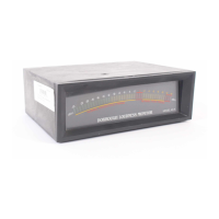
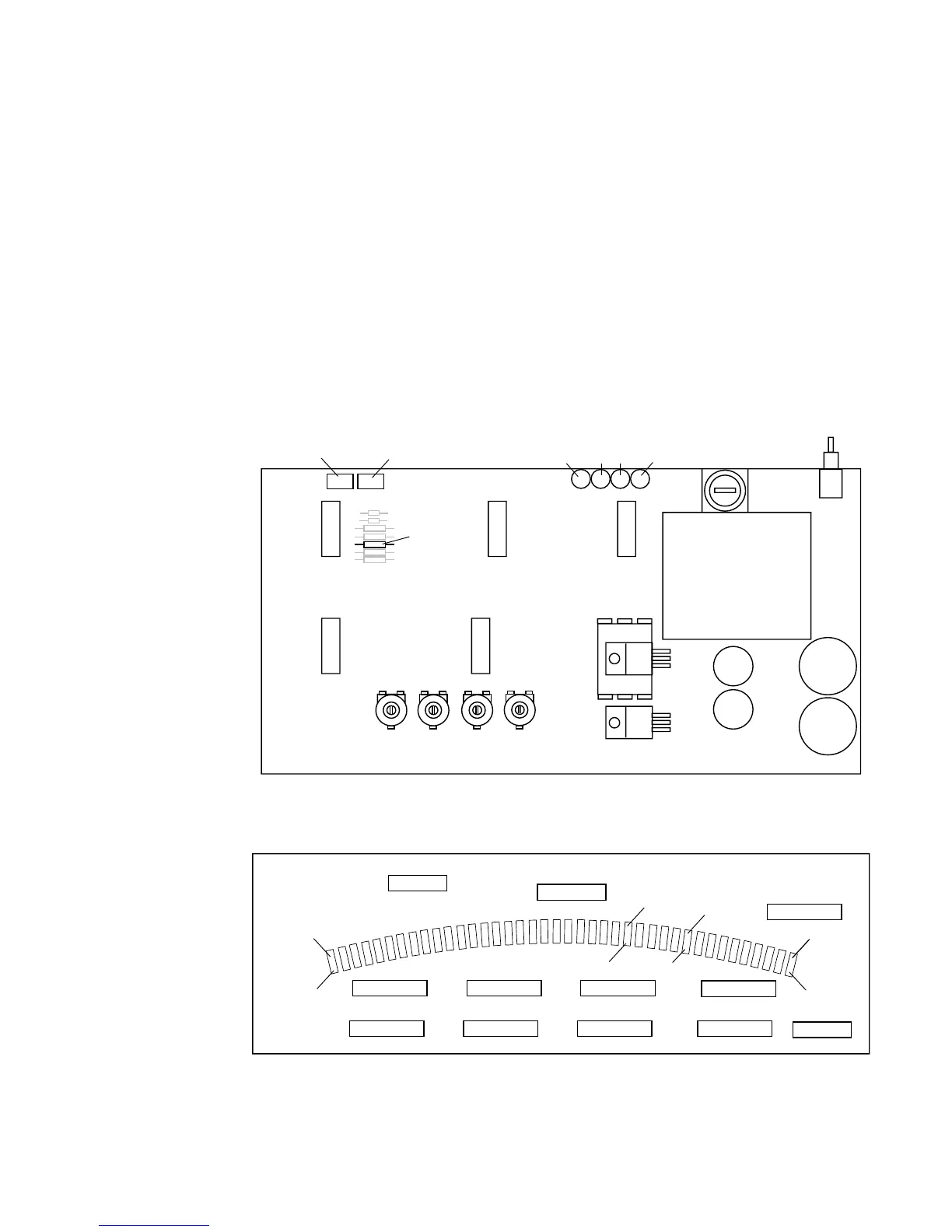
Fig. 15. Simplified view of key alignment components on Model 40-A (40-B)
circuit boards.
VR44 VR48 VR49 VR46
DS2 DS3DS1
R18
DS4
VR14 VR13
-25 dB (A)
+14 dB (A)
+5 dB (A)
LED DRIVER BOARD
POWER & SIGNAL BOARD
0 dB (A)
-36 dB (B)
+3 dB (B)
-11 dB (B) -6 dB (B)