14
"B" Type Monitor Alignment Procedure
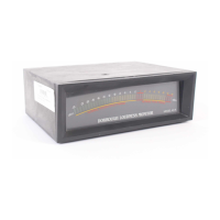
1. Connect the output from a test oscillator to the meter’s left input termi-
nals (see Fig. 1 ).
2. Feed a 1000 Hz sine-wave, at a reference level of “0” dB, into the meter.
3. Adjust the left input gain control VR-13 so that DS-1 is off and DS-2, -3, -4
are on.
4. Adjust the input signal to -25 dB.
5. Adjust the low PERSISTENCE level control VR-44 so only the first LED
(-36 dB on meter scale) at the bottom of the PERSISTENCE scale is
illuminated.
6. Adjust the low PEAK level control VR-46 so only the first LED (-36 dB on
meter scale) at the bottom of the PERSISTENCE scale brightens.
NOTE: This indicates that both the PEAK and the PERSISTENCE drivers are
providing current to this LED.
7. Change the input signal to +5 dB (a 30 dB increase).
8. Adjust the high PERSISTENCE level control VR-48 so that the bargraph
illuminates LEDs up to and including the -6 dB LED.
9. Adjust the high PEAK level control VR-49 until the -6 dB LED brightens.
NOTE: This indicates that both the PEAK and the PERSISTENCE drivers are
both providing current to this LED.
10. Increase input signal to +14 dB and observe that the +3 dB LED illumi-
nates.
NOTE: The +3dB LED should indicate drive from both PEAK and PERSIS-
TENCE drivers.
11. Decrease input signal to +13 dB ; observe that the +3 dB LED turns off.
12. Decrease input signal to +4 dB and adjust VR-13 for -11 dB onthe scale.
13. Then, feed input signal of +4 dB to right input terminals, and adjust
VR-14 for -11 dB on the scale. This duplicates the factory settings.
14. After both channels have been aligned, follow the procedure for setting-
up the operating level as described in the Initial Set-Up section (see
Installation).
Once you have completed this procedure, re-assemble the meter and place
the unit back in service.
☛
☛
☛