Instruction manual
Printer overview
1
2
3
4
5
6
7
8
9
10
11
12
13
14
15
1
2
3
4
5
6
7
8
9
10
11
12
13
14
15
2
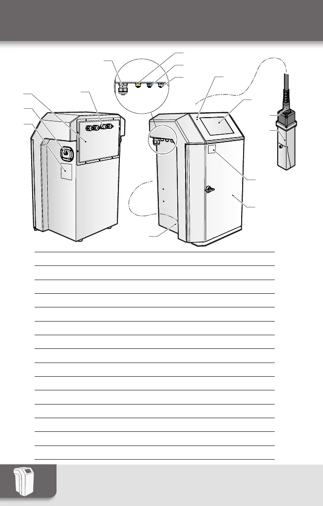
1 Manufacturer’s plate
2 Power supply inlet
3 Access to the electrical compartment
4 Cable glands: other connections (Serial/Parallel Link)
5 Cable glands: Ethernet
6 Connection interface: Warning (yellow)
7 Connection interface: Encoder (blue)
8 Connection interface: Detection cell (black)
9 Power-On LED
10 Operator interface
11 Umbilical
12 Print head
13 Identification label (serial no.)
14 Hydraulics compartment
15 Plant air connector
 Loading...