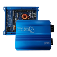
The JP84 is a full-range digital multi-channel amplifier designed for car audio systems. It is capable of stable operation into 2-ohm stereo or 4-ohm bridged loads, utilizing high-speed MOSFET power supply technology. The amplifier features variable high-pass and low-pass filters, as well as a crossover multiplier, offering flexible sound tuning options. It incorporates a band-pass filter and 4-way protection circuits to safeguard against thermal issues, high and low voltage, speaker shorts, and DC faults. The JP84 is built with a high-purity copper printed circuit board and includes 4-gauge power/ground terminals for robust connections.
Important Technical Specifications:
- Rated Power Output: JP-84
- RMS Power, 2 ohms: 120W x 4 (14.4V)
- RMS Power, 4 ohms: 90W x 4 (14.4V)
- RMS Power, 4 ohms Bridged: 284W x 2
- Frequency Response: 10Hz - 40KHz
- High Pass Filter: 20Hz - 800Hz
- High Pass Filter Multiply: x1, x10 (200Hz - 8KHz)
- Low Pass Filter: 50Hz - 800Hz
- Low Pass Filter Multiply: x1, x10 (500Hz - 8KHz)
- Input Sensitivity: 6V - 0.2V
- Signal to Noise Ratio: 95dB <
- T.H.D @ 4 ohms: less than 0.1%
- Fuse Rating: 60A
- Length (inches): 7.87"
- Width x Height (inches): 7.4" W x 2.24" H
Usage Features:
The JP84 requires careful installation, particularly regarding power connections. It is not supplied with internal fuses, so users must install an in-line fuse holder from the positive terminal of the battery. This fuse holder should be placed approximately 11 to 16 inches (300 to 400 mm) from the battery's positive terminal, ensuring no fuse is in the holder during initial connection.
Power Connections:
- +12V Power: Connect the amplifier's +12V terminal to the battery's positive terminal using a cable of the same diameter as the ground cable. Ensure the in-line fuse holder is installed correctly.
- Ground (GND): Disconnect the battery before connecting the GND terminal to the car's chassis. The ground cable should be as short as possible (not exceeding 20 inches) and connected to a rust-free, paint-free, and grime-free surface. For high-power amplifiers, it is recommended to connect the ground directly to the negative (-) battery terminal.
- Remote (REM): Connect the amplifier's REM terminal to the power antenna terminal or a dedicated remote turn-on wire (12 or 16 gauge electrical wire).
The amplifier features input connections for CH1, CH2, CH3, and CH4. Each channel pair (CH1/2 and CH3/4) has independent controls for:
- Gain: Adjustable from 6V to 0.2V.
- HPF (High Pass Filter): Adjustable from 20Hz to 800Hz, with a multiplier (x1 or x10) extending the range to 200Hz to 8KHz.
- LPF (Low Pass Filter): Adjustable from 50Hz to 800Hz, with a multiplier (x1 or x10) extending the range to 500Hz to 8KHz.
- ON/OFF switches for both HPF and LPF.
Speaker Connections:
The manual illustrates three speaker connection scenarios:
- Speaker Connection 1 (Stereo): Connects two speakers (8-4 ohms) to CH1/2 and CH3/4 terminals.
- Speaker Connection 2 (Bridged): Connects two speakers (4-2 ohms) in a bridged configuration, one to CH1/2 and one to CH3/4.
- Speaker Connection 3 (Bridged with Subwoofer): Connects two speakers (4-2 ohms) to CH1/2 and CH3/4, and a single subwoofer (8-4 ohms) bridged across the CH3/4 terminals.
Maintenance Features / Trouble Shooting:
The JP84 incorporates state-of-the-art protection features to prevent damage from misuse or faulty conditions. If the amplifier senses excessive heat, short-circuited speakers, DC, or over-voltage, the protection indicator will light up, and the system will turn off. Users should turn all levels down and power off, then carefully check the installation for wiring mistakes or shorts. If the subwoofer is too loud, it may cause the speakers to rip and short the coil. If the amplifier shuts down due to excessive heat, it will work once it cools down. Users should check the Bass Remote and Temp Meter on hot days and review the suggested procedures.
No Output Troubleshooting:
- Check remote turn-on voltage at the amplifier and head unit. If remote turn-on voltage is low or non-existent, the amplifier will remain off.
- Check fuses at the battery side or external fuses and all wire connections.
- Check if the RCA input is properly connected.
Amplifier Shut Down (Protection) Troubleshooting:
- Check POWER, GND, and REMOTE wire connections and other wires for proper connection.
- If the input voltage is greater than 4V DC at the amplifier's RCA input, the amplifier will go into DC protect. Remove the RCA input cable in this case. Check if the amplifier comes out of protection. If it does, you may need to replace the head unit or signal processing source.
- If the amplifier overheats, the thermal protection will turn off the amplifier. It will work again after cooling down a little bit. Install an amplifier with better ventilation to allow it to cool.
- The JP-84 has a minimum working impedance of 2 ohms stereo or 4 ohms bridged.
- The JP-84 working voltage is 9V - 16Volts.
- Ensure the chassis and remote use the same GROUND.
Distortion & Noise Troubleshooting:
- Readjust the amplifier input gain level, which is printed on the endplate.
- Ensure a good ground connection for the amplifier and head unit.
- Use sufficiently shielded RCA interconnects and good RCA routing. Avoid running RCA signal wires near power cables.
- Check all ground connections of all other audio equipment.
Poor Response Troubleshooting:
- Check speaker wiring and reverse polarity.