10 DR
®
POWER GRADER
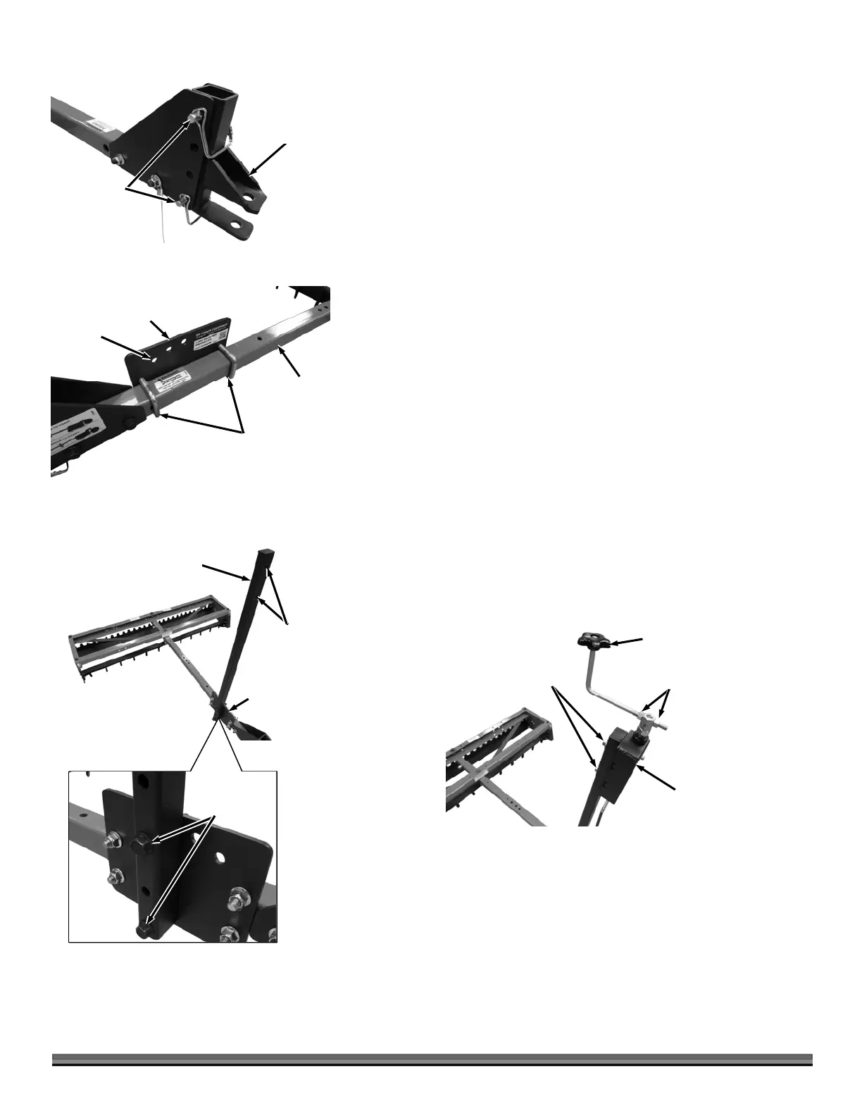
16. Position the Pin Hitch Assembly between the Hitch Adjustment Brackets
and secure with two Snap Safety Pins (Figure 14).
17. Secure the Sliding U-Bolt Backing Plate to the right side of the Tow Bar
(three holes facing forward) with two Post U-Bolts and four 3/8" Locknuts
using a 9/16" Wrench. Do not over tighten (Figure 15).
18. Install the Crank Post onto the Sliding U-Bolt Backing Plate with two 3/8-16
x 2-1/2" Bolts and Locknuts using two 9/16" Wrenches (Figure 16).
Note: The other two holes at bottom of the Crank Post can be used for height
adjustment as described in the “Crank Post Adjustment” section at the end of this
Chapter.
19. Attach the Height Adjust Control Box to the Crank Post with two 3/8-16 x 1-
1/2" Bolts, Lock Washers and Flat Washers using a 9/16" Wrench (Figure
17).
20. Insert a 3/8-16 Nut onto the threaded portion of the Crank Handle (about
3/4 of the way). Insert the Crank Handle into the hole at the top of the
Height Adjuster Control box and secure with another a 3/8-16 Nut using a
9/16" Wrench.
Note: Hold the Handle upright as you tighten the Nut against the Control Box hex.
Crank Post
Figure 16
Two Holes
Facing
Forward
Sliding U-Bolt
Backing Plate
Bolts and
Locknut
Sliding U-Bolt
Backing Plate
Figure 15
Post U-Bolts
and Locknut
Holes
Forward
Tow Bar
Pin Hitch
ssembly
Figure 14
Snap Safety
Pins
Height Adjust
Control Box
Figure 17
Bolt, Lock
Washer and
Flat Washer
Nuts
Crank
Handle