CONTACT US AT www.DRpower.com 11
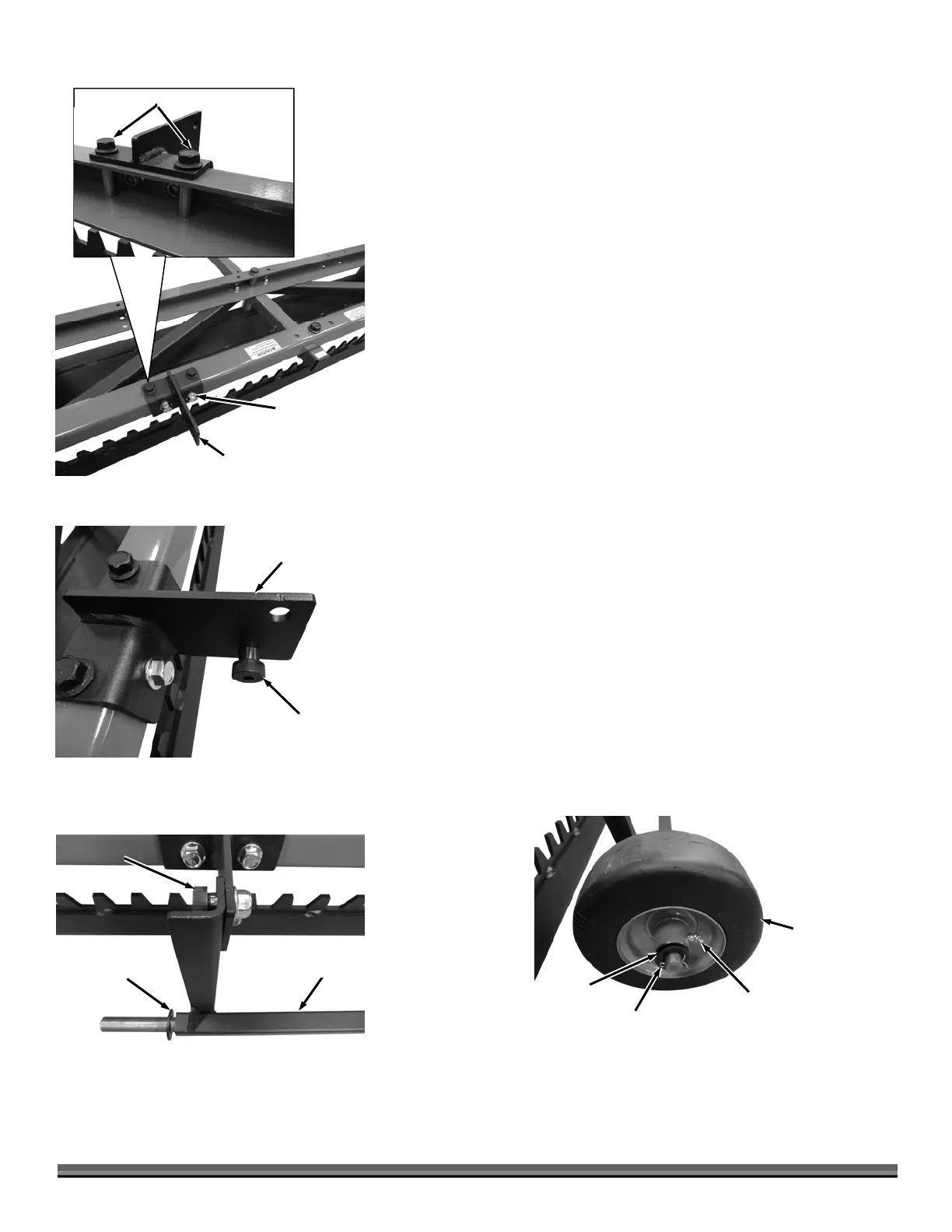
21. Secure the back side of the two Axle Brackets to the rear Crossmember with
two 3/8-16X 3/4" Bolts (with Washers) and Locknuts (with Washers) using
a Ratchet, Extension and 9/16" Socket on the inside and a 9/16" Wrench on
the inside (Figure 18).
22. Secure the top of the Axle Brackets with two 3/8-16 X 2-1/2" Bolts (with
Washers), Rail Spacers (inserted into crossmember) and Locknuts (with
Washer) using two 9/16" Wrenches.
23. Install a 1/2" X 3/8"L, 3/8-16 Shoulder Bolt (head facing left, towards
outside of machine) and Locknut to the left side Axle Bracket using a 1/4"
Allen Wrench and 9/16" Wrench (Figure 19).
24. Repeat step 23 for the right side Axle Bracket with the Shoulder Bolt facing
right, towards outside of the machine.
25. Position the Axle Assembly on the outside of the Axle Brackets (Figure 20).
Align the top holes of the Axle Brackets to the holes in the Axle Assembly
and secure with 1/2" X 3/8"L, 3/8-16 Shoulder Bolts (head facing out) and
Locknuts using a 1/4" Allen Wrench and 9/16" Wrench.
26. Place a .8" ID, 1.5" OD x .11" Washer onto both ends of the Axle Assembly.
27. Install a Wheel and .8" ID, 1.5" OD x .11" Washer on each end of the Axle
and secure with a Cotter Pin using Pliers to bend the ends (Figure 21).
Wheel
Figure 21
Grease
Fitting
Washer
Cotter Pin
xle
ssembly
Figure 20
Shoulder Bolt
Washer
Left Side
xle Bracket
Shoulder Bolt
and Locknut
Figure 19
xle Bracket
Figure 18
Bolts and
Locknut
Bolts, Rail Spacers and Locknuts
Rear
Crossmembe