12 DR
®
POWER GRADER
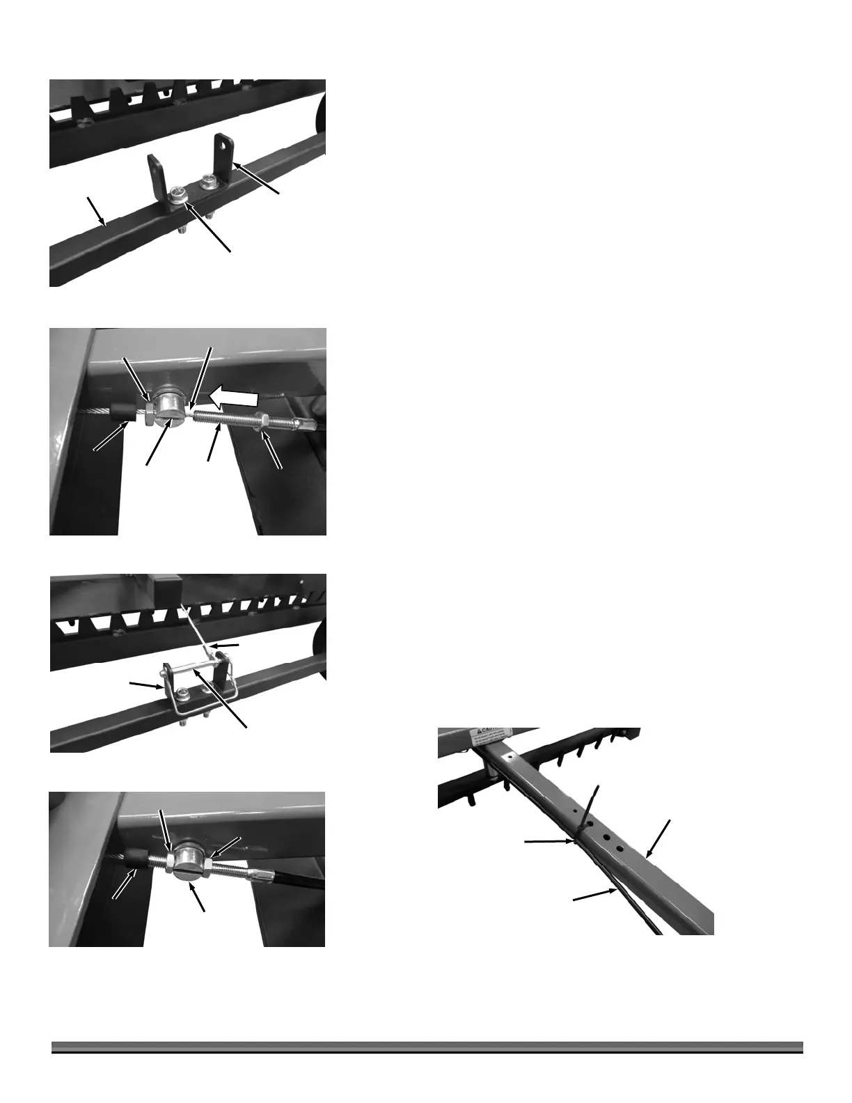
28. Install the Cable Spring Bracket onto the Axle Assembly with two 3/8-16 X
2" Bolts, Washers and Locknuts using two 9/16" Wrenches (Figure 22).
29. Insert the Height Adjust Cable under the front Crossmembers a position it
near the Cable Bushing (Figure 23).
30. Pull the Rubber Cap from the threaded Rod of the Cable Assembly and
unscrew the rear Jam Nut to remove it from the Threaded Rod.
31. Position the Cable into the Bushing slot and push the Threaded Rod into
the Bushing hole.
32. Adjust the front Jam Nut that is still on the Threaded Rod until the Eyelet at
the eyelet end of the Cable can be secured to the Cable Spring Bracket with
the 5/16" X 3" Snap Safety Pin (Figure 24).
33. Reinstall the Jam Nut and secure the Cable to the Bushing by tightening the
two Jam Nuts against the Bushing using two 1/2" Wrenches (Figure 25).
34. Reposition the Rubber Cap onto the end of the Threaded Rod.
35. Secure the Cable to the Tow Bar using the Cable Tie (Figure 26).
Height Adjust
Cable
Figure 26
Tow Bar
Cable Tie
Cable
Bushing
Figure 25
Rear Jam Nut
Front Jam Nut
Rubber
Cap
Snap Safety Pin
Figure 24
Cable Eyelet
Cable Sprin
Bracket
Cable
Bushing
Slot
Figure 23
Rear
am Nut
Front
am Nut
Rubber
Cap
Cable
Threaded
Rod
Cable Spring
Bracket
Figure 22
3/8-16 X 2" Flange
Bolts and Locknuts
xle
ssembly