12 DR
®
POWERWAGON
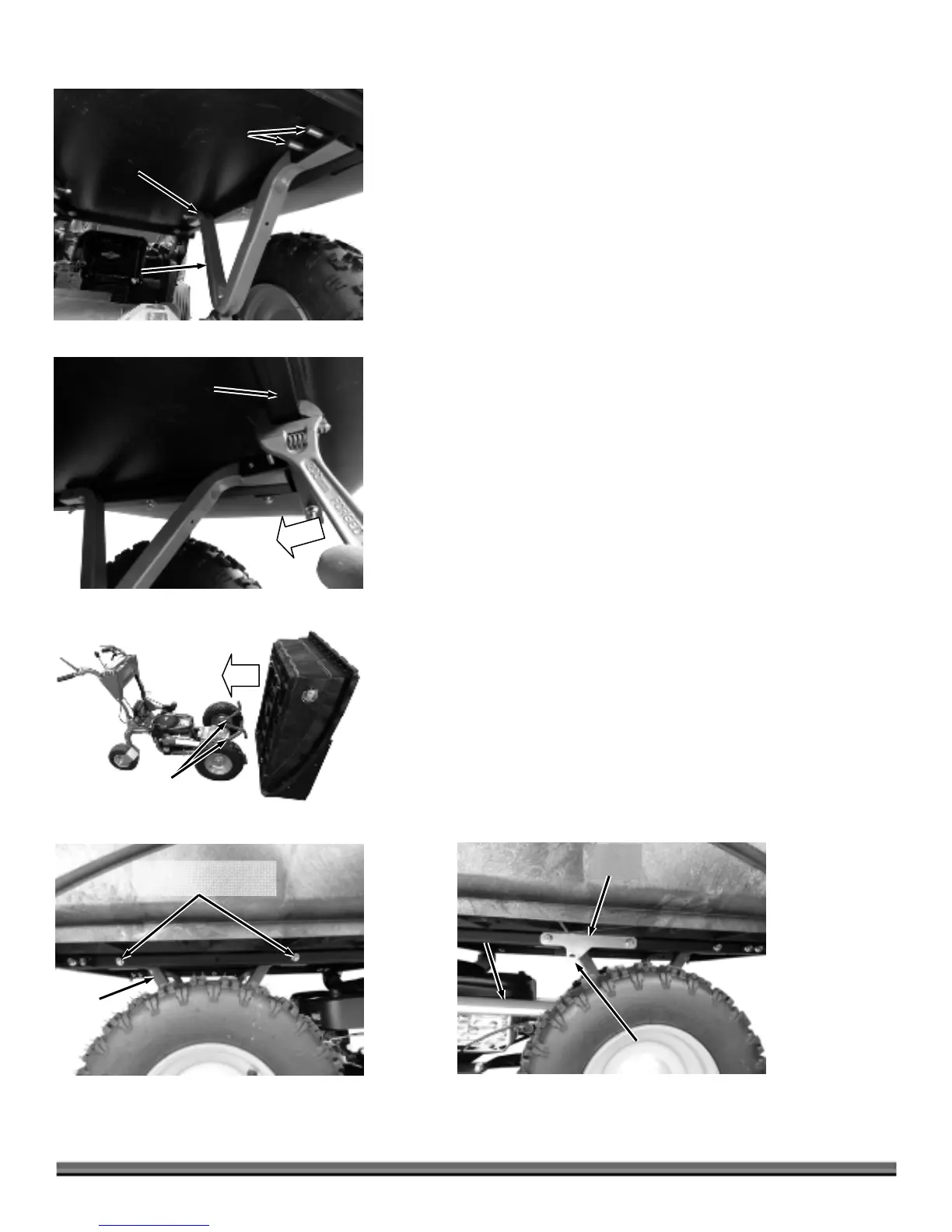
8. Turn the Front Bed Bolts through the Frame and Dump Arms at the front of
the Bed with a 1/2" Socket and Ratchet with Extension (Figure 14).
Note: If the Bolts are not aligning well with the holes in the Frame and Dump Arms,
a 10" Adjustable Wrench can be used on the front Frame Tube to align the holes
(Figure 15).
9. Secure the Front Bed Bolts to the Frame and Bed Supports with the four
5/16-18 Locknuts (you removed in step 5) using a 1/2" Wrench and 1/2"
Socket.
10. Secure the rear of the Dump Arms to the Frame with two 5/16-18 X 2-1/2"
Flange Bolts and Locknuts using a 1/2" Wrench and Socket (Figure 14).
Your Premier POWERWAGON assembly is complete. Proceed to the “Check the
Tire Pressure” section in this Chapter to continue with the setup of your
machine.
Pro and Pro-XL Bed - Assembly and Installation
If you are installing the Flatbed on your POWERWAGON, proceed to the
“Flatbed Installation” section in this Chapter.
PRO MODEL WITH HAND DUMP
1. Installing the Dump Handle on the Pro Model is the same as the Premier
Model. Refer to Steps 1 through 4 of “Premier Bed - Assembly and
Installation” if you do not have the Actuator Dump option.
PRO and PRO-XL MODELS
1. Place the Bed Assembly at the front of the machine with the Tailgate end
resting on the ground (Figure 16).
2. Move the Bed Assembly onto the Dump Arms and rotate the Bed back and
onto the Dump Arms.
PRO MODEL WITH HAND DUMP
1. Secure the Bed Frame to the Dump Arms with four 5/16-18 X 2-1/2" Flange
Bolts and Locknuts using a 1/2" Wrench and 1/2" Socket with Ratchet and
Extension (Figure 17).
PRO-XL MODEL ACTUATOR DUMP
1. For the following steps the Actuator Bracket must be positioned on the right
hand side of the Frame with the mounting hole towards the Actuator (Figure
18).
ctuator
Bracket
Figure 18
ctuato
Mounting Hole
(Facing Actuator)
Dump
rm
Figure 17
5/16-18 X 2-1/2" Flange
Bolts and Locknuts
Bed
ssembly
Figure 16
Dump
rms
Frame
Tube
Figure 15
Dump
rms
Figure 14
Front Bed
Bolt
Rear Bed
Support
Bolt

 Loading...